A new and old bridge joint structure system and construction method

A splicing seam and system technology, applied in bridges, bridge construction, bridge parts, etc., can solve problems such as obstacles to vehicle wheel changes, bridge deck height difference, damage, etc., to increase friction coefficient, excellent water release performance, and avoid slipping Effect

Active Publication Date: 2022-05-03
杭州市市政设施管理中心 +1
View PDF8 Cites 0 Cited by
  • Summary
  • Abstract
  • Description
  • Claims
  • Application Information

AI Technical Summary

Problems solved by technology

Although the appearance is beautiful when it is newly built, there are many shortcomings, specifically: because the bridge deck at the joint of the old and new bridges is under the action of uneven load, the bridge deck of the new and old bridge has a height difference, which in turn causes the asphalt at the joint of the old and new bridges to be damaged. Concrete surface cracked, damaged, leaking water
[0004] Although TST elastomer has the characteristics of simple structure and convenient construction, there are many shortcomings, specifically: TST elastomer has low strength, is easy to deform, and cannot return to its original shape after deformation; TST elastomer has poor durability and is prone to cracking, damage and leakage. Water; TST elastomer surface is smooth, low friction coefficient, easy to slip when driving
[0005] The stress structure of the longitudinal section steel expansion joints is reasonable, but there are many deficiencies, specifically: the longitudinal expansion joints are not beautiful, and the longitudinal expansion joints need regular maintenance; The bridge deck has a height difference, which is manifested by the height difference of the steel on both sides of the longitudinal steel expansion joint, and the splicing seam jumping, which seriously hinders the vehicle wheels from changing lanes and affects driving safety.

Method used


Image

  • A new and old bridge joint structure system and construction method
  • A new and old bridge joint structure system and construction method
  • A new and old bridge joint structure system and construction method

Examples


Embodiment Construction

[0021] The present invention will be further described below in conjunction with the accompanying drawings.

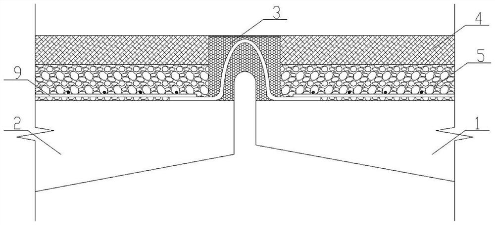
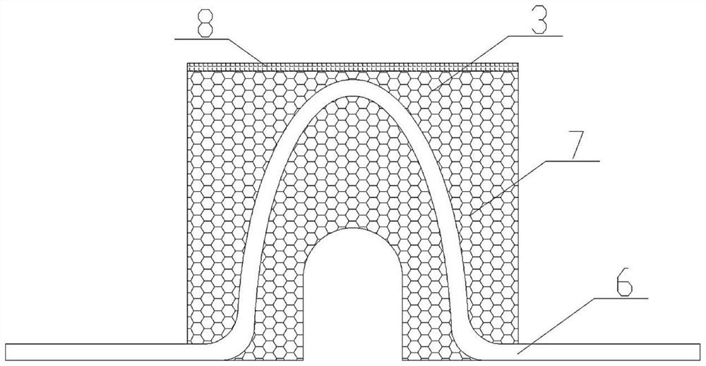
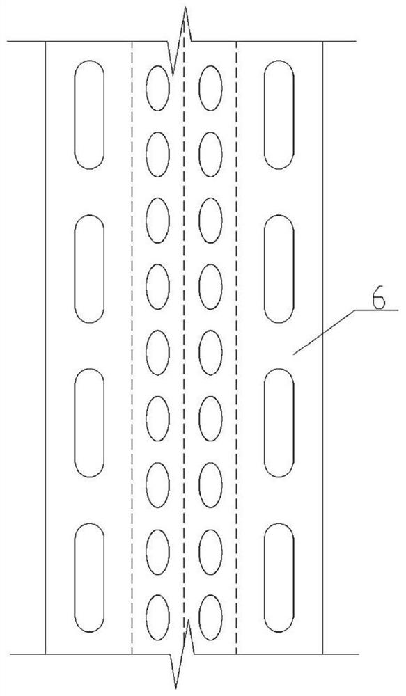
[0022] like figure 1 As shown, a kind of joint structure system of new and old bridges proposed by the present invention mainly includes new and old bridge decks, joint components, asphalt concrete surface course and reinforced concrete pavement, and the joint components include arched Porous steel plate connectors, and the middle part is pre-embedded in a rectangular polyurea elastomer, the upper surface is sprayed with a polyurea wear-resistant layer, and the porous steel plates on both sides are exposed. The porous steel plates on both sides of the splicing joint are welded to the extended steel bars of the bridge deck of the old and new bridges, and the micro-expansion steel fiber rapid-hardening sulfoaluminate cement concrete is poured on the welded joints, and finally the bridge deck asphalt concrete is paved together with the bridge deck of the old and new bridg...


PUM


Abstract

The invention discloses a joint structure system and construction method of a new and old bridge, and belongs to the technical field of bridge structure design and construction. The structural system is mainly composed of new and old bridge decks, joint components, asphalt concrete surface and reinforced concrete pavement. Prefabricate the arched porous steel plate, and pre-embed the middle part in the rectangular polyurea elastomer, and expose the porous steel plate on both sides to obtain the prefabricated splicing joint component; weld the perforated steel plate on both sides of the prefabricated splicing joint component to the old and new On the extended steel bars of the bridge deck, micro-expansion steel fiber rapid hardening sulfoaluminate cement concrete is poured on the welded joints, and finally the bridge deck asphalt concrete is paved to be flush with the upper surfaces of the old and new bridge decks and joint members. The invention is simple in construction, can ensure a better connection between the old and new bridge decks and splicing joint members, and can adapt to the settlement difference of the old and new bridges and the deformation height difference under uneven loads, so that the bridge is durable and has good water resistance.

Description

technical field [0001] The invention relates to the technical field of bridge engineering, in particular to a structural system and a construction method of a new-old bridge splicing joint. Background technique [0002] With the rapid growth of car ownership, a large number of roads need to be widened to meet the traffic demand, and a large number of bridges are also facing the need for widening, and the bridge deck joints between the new bridge and the old bridge have not been very good for a long time s solution. The traditional splicing joints of new and old bridges are mainly continuous bridge decks at the splicing joints, TST elastomer filling in the splicing joints, and longitudinal steel expansion joints. [0003] The bridge deck is continuous at the joint, that is, the bridge deck of the old and new bridges is disconnected at the joint, and the asphalt concrete surface layer and the reinforced concrete pavement are continuous at the joint. Although the appearance i...

Claims


Application Information

Patent Timeline
Patent Type & Authority Patents(China)
IPC IPC(8): E01D19/06E01D19/12E01D21/00
CPCE01D19/06E01D19/125E01D21/00
Inventor 仲玉芳叶茂勇方伟万罗为袁斌孙元孟利吉郑有华姜群李茜茜
Owner 杭州市市政设施管理中心
Why Eureka
Try Eureka