Directional cooling preparation device for microstructured biomaterials

A biological material and preparation device technology, which is applied in household refrigeration devices, cooling fluid circulation devices, lighting and heating equipment, etc., can solve the problem that the cooling device cannot guide the cooling material cooling speed in a directional way, and achieve adjustable cooling speed and cooling process , Cooling speed is accelerated, and the effect of high repeatability

Active Publication Date: 2021-12-21
SICHUAN UNIV
View PDF5 Cites 0 Cited by
  • Summary
  • Abstract
  • Description
  • Claims
  • Application Information

AI Technical Summary

Problems solved by technology

[0005] The purpose of the present invention is to provide a directional cooling preparation device for microstructured biological materials, which solves the problem that the existing cooling device cannot conduct directional cooling and accurately control the cooling speed of materials

Method used


Image

  • Directional cooling preparation device for microstructured biomaterials
  • Directional cooling preparation device for microstructured biomaterials
  • Directional cooling preparation device for microstructured biomaterials

Examples


Embodiment 1

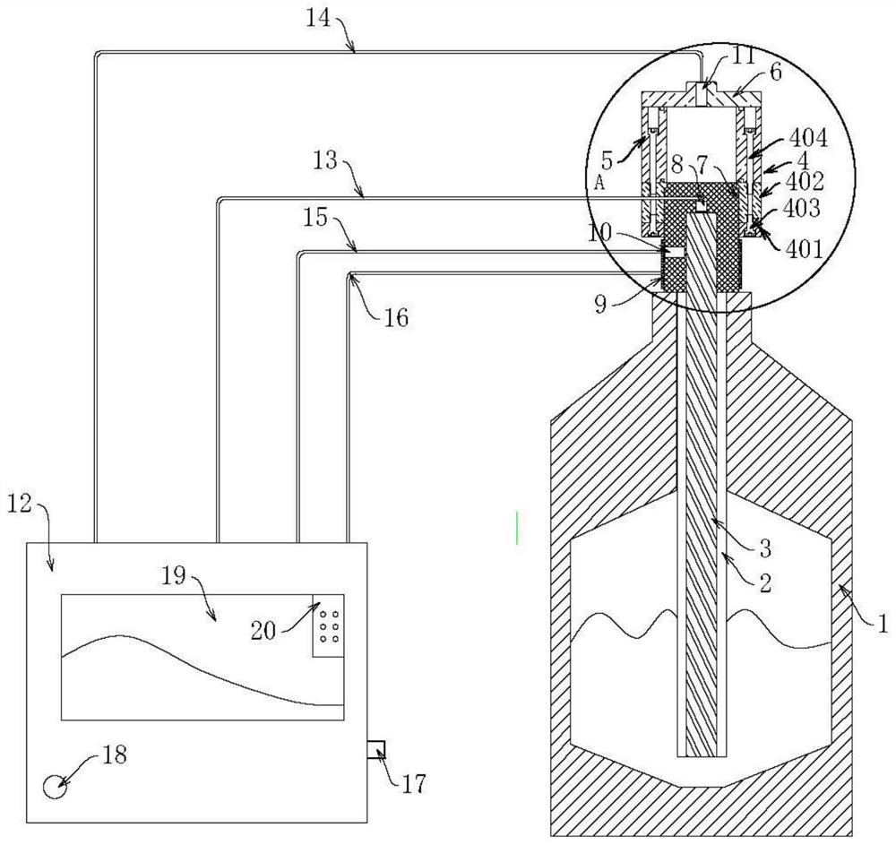
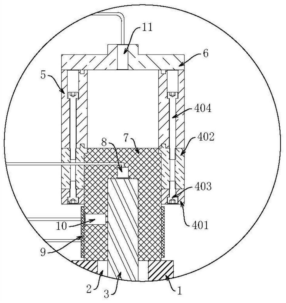
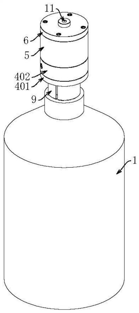
[0031] A preparation device for directional cooling of microstructured biological materials, comprising a cold source tank 1, the cold source can be liquid nitrogen, and the cold source tank 1 is provided with a placement cylinder 2, the placement cylinder 2 is a cavity structure with one end closed and one end open, for placing A part of the tube 2 can be fixed on the inner wall of the cold source tank 1 by welding, but the other part of the tube 2 is suspended in the cold source tank 1, and one end of the tube 2 extends to the cold source tank 1 At the opening of the placement cylinder 2, a cooling mechanism including the first cooling column 3 is fixed, the first cooling column 3 can be fixedly connected to the placement cylinder 2 by but not limited to welding, the first cooling column 3 One end extends to the outside of the cold source tank 1 and is inserted into the sealing member 4. The sealing member 4 is arranged at the opening of the cold source tank 1 and seals the c...

Embodiment 2

[0035]This embodiment is a continuous improvement on the basis of Embodiment 1. On the basis of the technical solution of the embodiment, the first temperature sensor 8 is provided at the end of the first cold guide column 3 outside the cold source tank 1, and the second guide column 3 is provided with a first temperature sensor 8. The outer wrapping of cold column 7 is provided with heating ring 9, and the side of heating ring 9 close to the second cooling column 7 is fixedly provided with heating temperature sensor 10, and heat preservation cover 6 is provided with the second temperature sensor 11 that penetrates, and the first temperature sensor 8. The second temperature sensor 11, the heating temperature sensor 10, and the heating ring 9 are electrically connected to the corresponding corresponding parts of the console 12 through the first temperature sensing line 13, the second temperature sensing line 14, the heating temperature sensing line 15, and the heating power line ...


PUM


Abstract

The invention discloses a directional cooling preparation device for microstructured biological materials, which relates to the technical field of microstructured biological materials. Cold column, one end of the first cooling column extends to the outside of the cold source tank and is inserted into the seal, the seal seals the cold source tank, the seal communicates with the material chamber, and the outlet of the material chamber is provided with a sealed thermal insulation cover , forming a directional conduction structure in which the cold source transfers energy to the material chamber along the first cooling column. The material chamber that can accommodate the material is set at the part of the device, so that the material is in contact with the first cooling column, the energy of the cold source is transferred to the material through the directional guidance of the first cooling column, and the direction of the cooling source is controlled, thereby controlling the ice crystals. Growth direction, reducing the difficulty of material preparation, high repeatability, good reproducibility, and controllable process.

Description

technical field [0001] The invention relates to the technical field of microstructure biomaterials, in particular to a directional cooling preparation device for microstructure biomaterials. Background technique [0002] Bone regeneration materials have always been one of the research hotspots of clinicians at home and abroad. The preparation of regular microstructure biomaterials is based on the frontier of bone tissue engineering development and has important bionic and application values. There are many ways to prepare them. For example, using existing Controlled cooling device, through the vacuum freeze-drying method, the solvent in the material is frozen at a low temperature, and the ice crystals in the material are directly sublimated under vacuum or low pressure to obtain a material with a certain microporous structure. The principle of this preparation method Simple, but the disadvantages are: (1) It cannot achieve directional cooling, that is, control the growth dir...

Claims


Application Information

Patent Timeline
Patent Type & Authority Patents(China)
IPC IPC(8): F25D3/10F25D23/00F25D29/00
CPCF25D3/10F25D23/00F25D29/00F25D2700/12
Inventor 于海洋王中熠谭欣
Owner SICHUAN UNIV
Why Eureka
Try Eureka