High-efficiency dust removal equipment for pcb circuit boards for electronic technology development
A technology of PCB circuit boards and dust removal equipment, which is applied in the direction of dust removal, cleaning methods and tools, cleaning methods using tools, etc., can solve problems such as inconvenient operation, replacement of PCB circuit boards, and inability to remove dust from PCB circuit boards in batches, and achieve The effect of simple and stable structure and high universal applicability
- Summary
- Abstract
- Description
- Claims
- Application Information
AI Technical Summary
Problems solved by technology
Method used
Image
Examples
Embodiment 1
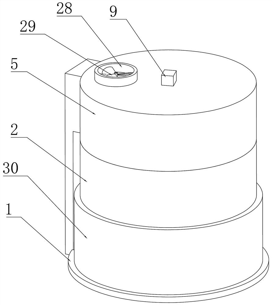
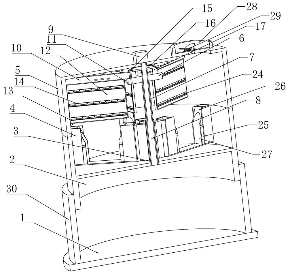
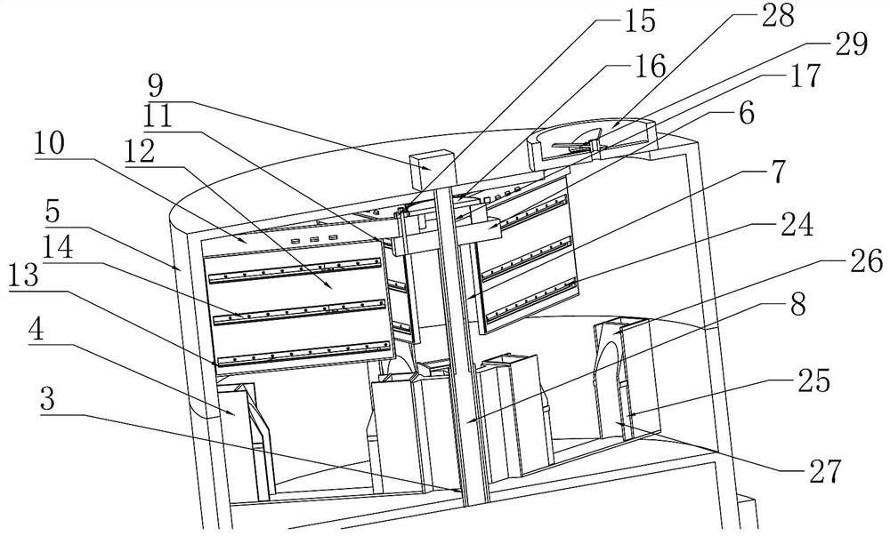
[0031] Embodiment 1, the present invention is a high-efficiency dust removal device for PCB circuit boards for electronic technology development, including a base frame 1, the base frame 1 provides a fixed support foundation for subsequent structures, and the base frame 1 is placed on the ground. The supporting base 2 is slidably connected up and down on the base frame 1, and the supporting base 2 and the base frame 1 are threadedly connected, and the supporting base 2 is rotated to make the supporting base 2 along the The base frame 1 slides up and down, the upper end of the support base 2 is coaxially fixedly connected with a connecting shaft 3, and a plurality of bearing brackets 4 are fixedly connected to the connecting shaft 3, so that the bearing bracket 4 and all the bearing brackets 4 are fixedly connected. The connecting shaft 3 slides synchronously, and the bearing bracket 4 is used to support the PCB circuit board, and limit and fix the PCB circuit board;
[0032] T...
Embodiment 2
[0036] Embodiment 2, on the basis of Embodiment 1, in the process of dust removal and cleaning of the PCB circuit board, only one side of the PCB circuit board can be treated, and the double-sided dust removal treatment cannot be effectively performed. Therefore, this embodiment provides a structure for double-sided dust removal. Specifically, the cantilever frame 10 and the lifting disc 6 are rotatably connected, and the upper end of the cantilever frame 10 is fixedly connected with a pinion 15, so The rotation of the pinion gear 15 drives the cantilever frame 10 to rotate synchronously to realize the rotation of the cantilever frame 10. The rotation of the cantilever frame 10 drives the wiping plate 11 to rotate synchronously, and the wiping plate 11 rotates The process realizes the cleaning and dust removal of the adjacent PCB circuit boards. The upper end of the lifting disk 6 is coaxially connected with the driving toothed plate 16, and the driving toothed plate 16 meshes ...
Embodiment 3
[0038] Embodiment 3, on the basis of Embodiment 1, in order to facilitate the cleaning of the wiping plate 11 and the replacement of the wiping plate 11, this embodiment provides a removable wiping plate 11. Specifically, the wiping plate 11 and the cantilever frame 10 are detachably connected, the cantilever frame 10 is provided with a connecting rail 20, and the upper end of the wiping plate 11 is fixedly connected with the The connecting block 21 matched with the connecting rail 20, the connecting block 21 is slidably connected with a locking oblique block 22, the locking oblique block 22 and the connecting block 21 are connected by a spring, and the connecting block 22 is connected to the connecting block 21. The connecting rail 20 is provided with a locking groove 23 that cooperates with the locking inclined block 22. Under the cooperation of the locking groove 23 and the locking inclined block 22, the wiping plate 11 is fixed. limit.
PUM
 Abstract
Description
Claims
Application Information
 - R&D
- Intellectual Property
- Life Sciences
- Materials
- Tech Scout
- Unparalleled Data Quality
- Higher Quality Content
- 60% Fewer Hallucinations
Browse by: Latest US Patents, China's latest patents, Technical Efficacy Thesaurus, Application Domain, Technology Topic, Popular Technical Reports.
© 2025 PatSnap. All rights reserved.Legal|Privacy policy|Modern Slavery Act Transparency Statement|Sitemap|About US| Contact US: help@patsnap.com


