A method for removing traces on the surface of an automobile crankshaft

A processing method and crankshaft technology, applied in the direction of metal material coating process, coating, etc., can solve the problems of reducing the peeling off of anti-corrosion layer, and achieve the effect of speeding up efficiency, improving strength, and accelerating the speed of cooling and solidification.

Active Publication Date: 2021-12-21
JIANGSU WANLI MACHINERY
View PDF8 Cites 0 Cited by
  • Summary
  • Abstract
  • Description
  • Claims
  • Application Information

AI Technical Summary

Problems solved by technology

[0007] Aiming at the problems existing in the prior art, the object of the present invention is to provide a method for removing traces on the surface of an automobile crankshaft. Before coating the anticorrosion layer, the crankshaft is magnetized, and repair microspheres are laid. Under operation, the repairing microspheres near the microcracks are brought close to the cracks. At this time, the repairing microspheres are heated and melted by laser cladding, and the pre-melted powder inside is flowing into the micromarks on the surface of the crankshaft. After solidification, it forms The repaired bottom layer with colored spots is then coated with an anti-corrosion layer. Compared with the existing technology, the micro-cracks are effectively repaired, and the existence of air in the anti-corrosion layer is effectively eliminated, so that the repaired bottom layer and anti-corrosion layer on the crankshaft surface can The anti-corrosion layer can protect it together, which can significantly reduce the occurrence of peeling off of the anti-corrosion layer. At the same time, the repair of cracks can also significantly improve the strength of the crankshaft itself, so that it is not easy to increase the cracks during long-term use.

Method used


Image

  • A method for removing traces on the surface of an automobile crankshaft
  • A method for removing traces on the surface of an automobile crankshaft
  • A method for removing traces on the surface of an automobile crankshaft

Examples


Embodiment 1

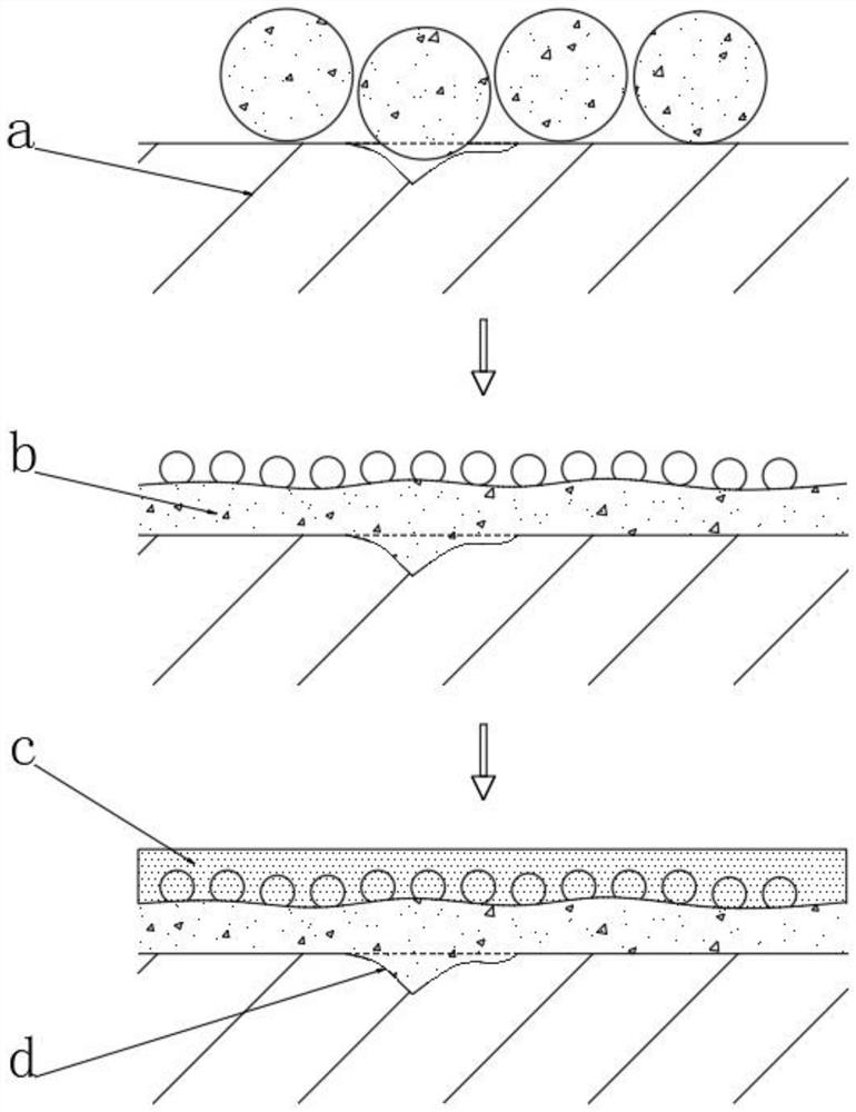
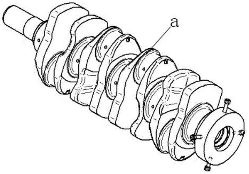
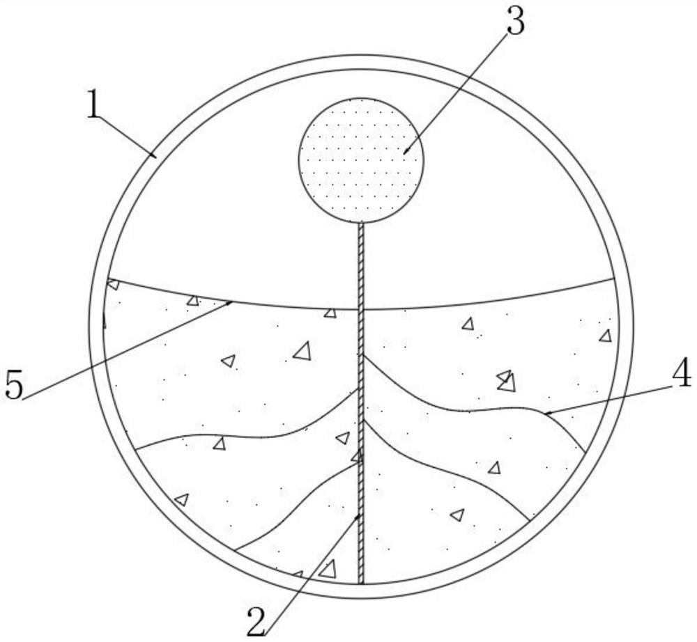
[0046] see Figure 1-2 In the figure, a represents the crankshaft, b represents the bottom layer of the repair, c represents the anti-corrosion layer, and d represents the micro-cracks on the surface of the crankshaft. A method for removing traces on the surface of an automobile crankshaft includes the following steps:

[0047] S1. First, pre-treat the crankshaft to be treated, and then dry it after treatment. The pre-treatment includes one or more of degreasing, degreasing and rust removal, which can effectively reduce the impurities on the surface of the crankshaft, so that the formed repair base layer and crankshaft The part of the surface contact is more uniform;

[0048] S2. Magnetizing the pre-treated crankshaft to make the crankshaft magnetic;

[0049] S3, then lay repair microspheres on the surface of the magnetic crankshaft to form a pre-repair layer, then adjust the thickness of the pre-repair layer until uniform, and the thickness of the pre-repair layer is 3-4mm; ...


PUM

PropertyMeasurementUnit
thicknessaaaaaaaaaa

Abstract

The invention discloses a method for treating automobile crankshaft surface by flowing traces, which belongs to the field of automobile crankshafts. It relates to a method for processing automobile crankshafts by flowing and removing traces. Under the operation of micro-adjustment treatment, the repair microspheres near the microcracks are brought close to the cracks. At this time, through laser cladding, the repair microspheres are heated and melted, and the pre-melted powder inside them shows flow dynamics and infiltrates into the micromarks on the surface of the crankshaft. , After solidification, a repair base layer with colored spots is formed, and then the anti-corrosion layer is applied. Compared with the existing technology, micro-cracks are effectively repaired, and the existence of air in the anti-corrosion layer is effectively eliminated, so that during long-term use, the surface of the crankshaft Repairing the bottom layer and the anti-corrosion layer work together to protect it, significantly reducing the occurrence of the anti-corrosion layer falling off, and at the same time repairing the cracks can also significantly improve the strength of the crankshaft itself, making it less likely to cause cracks to increase during long-term use Case.

Description

technical field [0001] The invention relates to the field of automobile crankshafts, in particular to a method for treating surface flow marks of automobile crankshafts. Background technique [0002] The most important component in a crankshaft engine. It bears the force transmitted by the connecting rod and converts it into torque through the crankshaft output and drives other accessories on the engine to work. The crankshaft is subjected to the joint action of the centrifugal force of the rotating mass, the periodically changing gas inertial force and the reciprocating inertial force, so that the crankshaft is subjected to the bending torsional load. Therefore, the crankshaft is required to have sufficient strength and rigidity, and the surface of the journal needs to be wear-resistant, work evenly, and have good balance. [0003] In order to reduce the mass of the crankshaft and the centrifugal force generated during movement, the crankshaft journal is often made hollow...

Claims


Application Information

Patent Timeline
Patent Type & Authority Patents(China)
IPC IPC(8): C23C24/10
CPCC23C24/103
Inventor 谢善忠殷文元
Owner JIANGSU WANLI MACHINERY
Why Eureka
Try Eureka