
Assembly type reinforced concrete frame beam-column joint connecting structure

A technology of reinforced concrete and beam-column joints, which is applied to truss structures, structural elements, and long-strip structural members for load-bearing, etc. Difficulty in quality inspection and other issues, to achieve the effect of clear node force transmission path, reliable detection method, and simple construction

Pending Publication Date: 2021-07-16
CCCC FHDI ENG
View PDF0 Cites 3 Cited by
  • Summary
  • Abstract
  • Description
  • Claims
  • Application Information

AI Technical Summary

Problems solved by technology

Among them, the grouting sleeve connection is widely used in actual engineering and the technology is relatively mature, but there are still problems such as on-site docking difficulties, difficulty in ensuring the quality of grouting in the sleeve, and difficulty in later quality inspection; The "Technical Regulations for Prefabricated Concrete Structures" JGJ1-2014 clearly stipulates that when the longitudinal steel bars are connected by grout anchor lap joints, the hole forming process of the reserved holes, the shape and length of the holes, the structural requirements, the grouting materials and the connected steel bars should be carried out. Experimental verification of mechanical properties and applicability
In particular, steel bars with a diameter greater than 20 mm should not be connected by grout anchor lap joints, and longitudinal steel bars directly bearing dynamic loads should not be connected by grout anchor lap joints; the reserved secondary pouring belt connection method is close to the cast-in-place effect, but on-site construction is inconvenient , Difficulty; the connection structure of pre-embedded steel joints is complicated, and the joint stiffness is difficult to achieve the same strength as that of pure concrete joints

Method used


Image

  • Assembly type reinforced concrete frame beam-column joint connecting structure
  • Assembly type reinforced concrete frame beam-column joint connecting structure

Examples


Embodiment Construction

[0032] In order to facilitate the understanding of the present invention, the present invention will be described more fully below with reference to the associated drawings. Preferred embodiments of the invention are shown in the accompanying drawings. However, the present invention can be embodied in many different forms and is not limited to the embodiments described herein. On the contrary, the purpose of providing these embodiments is to make the disclosure of the present invention more thorough and comprehensive.

[0033] It should be noted that when an element is referred to as being “fixed” to another element, it can be directly on the other element or there can also be an intervening element. When an element is referred to as being "connected to" another element, it can be directly connected to the other element or intervening elements may also be present. The terms "vertical," "horizontal," "left," "right," and similar expressions are used herein for purposes of ill...


PUM


Abstract

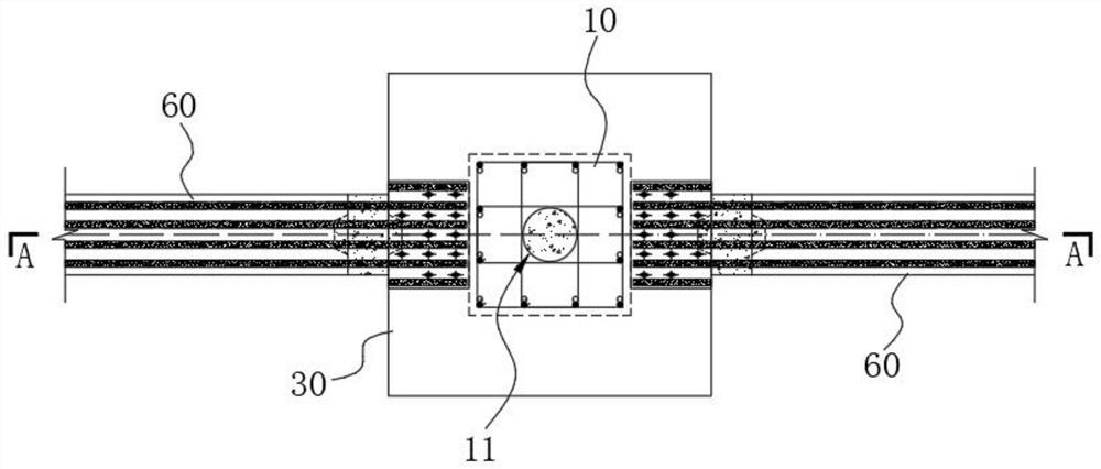
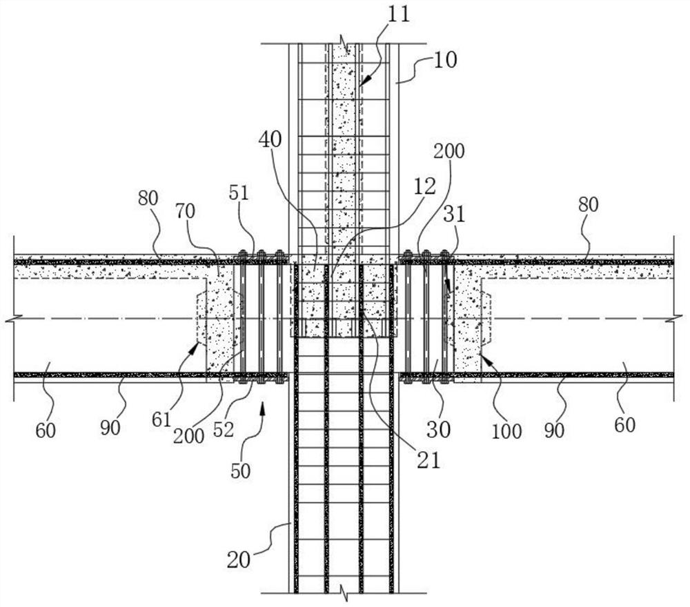
The invention provides an assembly type reinforced concrete frame beam-column joint connecting structure. The assembly type reinforced concrete frame beam-column joint connecting structure comprises a prefabricated column, a connecting steel plate set and prefabricated beams, the prefabricated column comprises a prefabricated upper column, a prefabricated lower column, a prefabricated column cap and a first post-pouring section, the prefabricated column cap is formed at the upper end of the prefabricated lower column, the first post-pouring section is formed inside the prefabricated column cap, and the prefabricated upper column is fixedly connected with the prefabricated lower column through the first post-pouring section; the connecting steel plate set is arranged on the outer side of the prefabricated column cap; and the prefabricated beams are arranged on one side of the prefabricated column cap in parallel at intervals, the prefabricated beams and the prefabricated column cap are connected through a second post-pouring section, a beam longitudinal bar set extends out of the end, facing the prefabricated column cap, of each prefabricated beam, and the beam longitudinal bar sets are locked and fixed to the connecting steel plate set through bolt assemblies. Splicing of the prefabricated column is achieved through lap joint of the prefabricated upper column and the prefabricated lower column and the first post-pouring section formed in the prefabricated column cap, and connection between the prefabricated beams and the prefabricated column achieves anchoring of the beam longitudinal bar sets through friction force formed by the beam longitudinal bar sets and the connecting steel plate set under the pretension action of high-strength bolt assemblies.

Description

technical field [0001] The invention relates to the field of structural engineering, in particular to an assembled reinforced concrete frame beam-column node connection structure. Background technique [0002] At present, the construction industry is undergoing a subversive revolution, that is, it is developing rapidly in the direction of construction industrialization and housing industrialization. The ascendant "prefabricated building" is an effective way to realize the industrialization of construction and housing. Today, the promotion of prefabricated buildings has risen to the level of national strategy, and has become an important means for the country to stabilize growth, promote reform, and adjust structure, as well as an important starting point for promoting the transformation and upgrading of the construction industry to industrialization, standardization, refinement, and new energy conservation. . [0003] The prefabricated concrete structure is one of the thre...

Claims


Application Information

Patent Timeline
Patent Type & Authority Applications(China)
IPC IPC(8): E04C3/20E04C3/34E04B1/20E04B1/21E04B1/58E04C5/01E04G21/14
CPCE04C3/20E04C3/205E04C3/34E04B1/20E04B1/21E04B1/215E04B1/58E04C5/01E04G21/14
Inventor 张立平
Owner CCCC FHDI ENG
Learn More