Cooling system for power electronic equipment
A cooling system, power electronics technology, applied in mechanical equipment, lighting and heating equipment, refrigerators, etc., can solve problems such as increasing failure rate, thermal fatigue of devices, and consuming large mechanical energy, and achieve the effect of increasing failure rate
- Summary
- Abstract
- Description
- Claims
- Application Information
AI Technical Summary
Problems solved by technology
Method used
Image

Examples
Embodiment 1
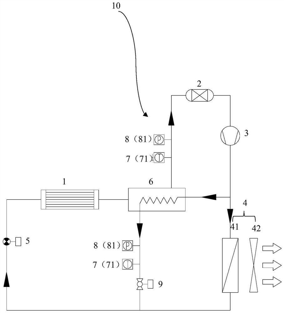
[0058] Such as figure 1 As shown, the cooling system 10 for power electronic equipment according to the embodiment of the present invention includes an evaporator 1 , a gas-liquid separator 2 , a compressor 3 and a condensing device 4 . Wherein, the outlet of the evaporator 1 is connected with the inlet of the gas-liquid separator 2 . The inlet of the compressor 3 is connected with the outlet of the gas-liquid separator 2 , and the outlet of the compressor 3 is connected with the inlet of the condensing device 4 . A throttling valve 5 is provided between the outlet of the condensing device 4 and the inlet of the evaporator 1 .
[0059] According to the cooling system for power electronic equipment according to the embodiment of the present invention, according to the real-time working conditions of the equipment to be cooled, the control function of the throttle valve is used to make the flow rate of the liquid working medium condensed by the condensing device greater than th...
Embodiment 2
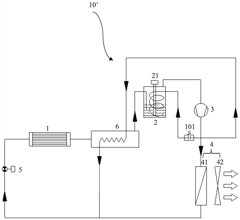
[0067] Such as figure 2 As shown, the cooling system 10' for power electronic equipment in the embodiment of the present invention, on the basis of the above-mentioned embodiment 1, is different in that:
[0068] The outlet of the compressor 3 is connected to the inlet of the gas-liquid separator 2 , and a control valve 101 is arranged between the outlet of the compressor 3 and the inlet of the gas-liquid separator 2 . In this structural form, the outlet of the cold side of the regenerator is in a state of a small amount of liquid, and the outlet of the hot side is in a state of subcooled liquid. The high-temperature steam from the outlet of the compressor is properly introduced into the gas-liquid separator for mixing and heat exchange, consuming it low-temperature liquid, so as to effectively adjust the amount of superheated steam entering the compressor and improve heat exchange efficiency.
[0069] Preferably, as figure 2 As shown, in this embodiment, the gas-liquid se...
Embodiment 3
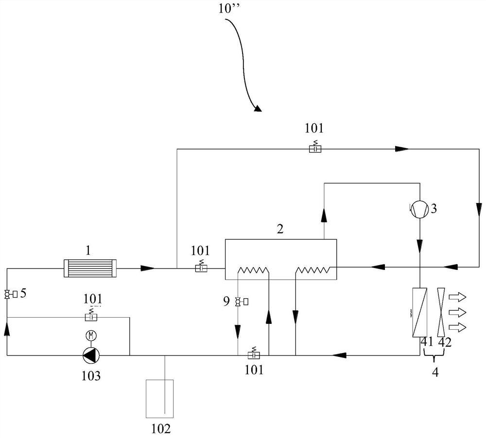
[0072] Such as image 3 As shown, the cooling system 10 "for power electronic equipment of the embodiment of the present invention includes an evaporator 1, a gas-liquid separator 2, a compressor 3 and a condensation device 4. Wherein, the outlet of the evaporator 1 is connected to the gas-liquid separator The inlet of 2 is connected. The inlet of compressor 3 is connected with the outlet of gas-liquid separator 2, and the outlet of compressor 3 is connected with the inlet of condensing device 4. There is a throttling between the outlet of condensing device 4 and the inlet of evaporator 1 valve 5.
[0073] According to the cooling system for power electronic equipment of the present invention, according to the real-time working conditions of the equipment to be cooled, the control function of the throttle valve is used to make the flow rate of the liquid working medium condensed by the condensing device greater than that required by the complete evaporation of the evaporator ...
PUM
 Abstract
Description
Claims
Application Information
 - Generate Ideas
- Intellectual Property
- Life Sciences
- Materials
- Tech Scout
- Unparalleled Data Quality
- Higher Quality Content
- 60% Fewer Hallucinations
Browse by: Latest US Patents, China's latest patents, Technical Efficacy Thesaurus, Application Domain, Technology Topic, Popular Technical Reports.
© 2025 PatSnap. All rights reserved.Legal|Privacy policy|Modern Slavery Act Transparency Statement|Sitemap|About US| Contact US: help@patsnap.com