
Municipal sludge and engineering slurry co-processing device and co-processing method thereof

A municipal sludge and co-processing technology, applied in sludge treatment, water/sludge/sewage treatment, grain treatment, etc., can solve the problem that the municipal sludge and engineering sludge cannot be fully mixed, affect the stability of the ball mill, and affect the work. Environmental quality and other issues, to achieve the effect of improving filter press dehydration performance, improving the quality of the working environment, and reducing work costs

Pending Publication Date: 2021-07-23
金茂(深圳)生态科技有限公司 +1
View PDF8 Cites 0 Cited by
  • Summary
  • Abstract
  • Description
  • Claims
  • Application Information

AI Technical Summary

Problems solved by technology

[0004] 1. The existing technology mainly adopts the method of high-speed stirring to mix municipal sludge and engineering mud evenly in batches, and the operating efficiency is low
Moreover, because the municipal sludge is relatively viscous, the energy consumption of the mixing process is high, and the fine sand in the engineering mud will accelerate the wear of the mixing paddle;
[0005] 2. During the use of the ball mill, the gears on the surface cannot be cooled and dissipated, which affects the stability of the ball mill, reduces the grinding efficiency, affects the grinding quality, and cannot ensure the full mixing of municipal sludge and engineering mud;
[0006] 3. After the ball mill fully mixes the municipal sludge and engineering mud, it is impossible to take out the mixed slurry conveniently, and the direct export may cause the slurry to splash, resulting in waste of slurry and affecting the quality of the working environment;
[0007] 4. After the plate and frame filter press is used to filter and dehydrate the mixed slurry, the mud cake cannot be quickly and conveniently taken out from the bottom of the filter press for recycling, which wastes manpower and material resources, and the work cost is high

Method used


Image

  • Municipal sludge and engineering slurry co-processing device and co-processing method thereof
  • Municipal sludge and engineering slurry co-processing device and co-processing method thereof
  • Municipal sludge and engineering slurry co-processing device and co-processing method thereof

Examples


Embodiment 1

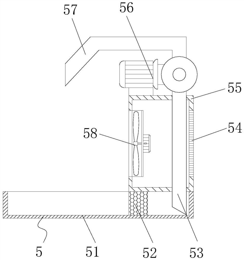
[0038] see Figure 1-8 , the present invention provides the following technical solutions: a municipal sludge and engineering mud co-processing device, comprising a ball mill 4, a plate and frame filter press 1 is arranged on one side of the ball mill 4, and a convenient cooling assembly 5 is arranged on the bottom end of the ball mill 4, The convenient cooling assembly 5 includes a collection tank 51, a fiber filter screen 52, a guide pipe 53, a mounting frame 55, a water pump 56 and a spray pipe 57, wherein the bottom end of the ball mill 4 is provided with a collection tank 51, and the inside of the collection tank 51 is provided with There is a fiber filter screen 52, the upper end of the collection tank 51 is provided with a mounting frame 55, the upper end of the mounting frame 55 is provided with a water pump 56, the bottom end of the water pump 56 is provided with a guide tube 53, and the upper end of the water pump 56 is provided with a spray pipe 57, During the worki...

Embodiment 2

[0042] The difference between this embodiment and Embodiment 1 is: further; an adjustment transfer assembly 3 is provided between the ball mill 4 and the plate and frame filter press 1, and the adjustment transfer assembly 3 includes a guide column 31, a dump box 32, and a screw rod 33 , stepping motor 34, driving gear 35, driving gear 35, mounting plate 37 and base plate 38, wherein, one side of ball mill 4 is provided with base plate 38, and one side of the upper end of base plate 38 is provided with stepping motor 34, step The output end of the motor 34 is provided with a driving gear 35, and one side of the driving gear 35 is provided with a screw mandrel 33, and the surface of the screw mandrel 33 is provided with a driven gear 36 corresponding to the driving gear 35, and the upper end of the base plate 38 is far away from the screw mandrel 33. One side is provided with a guide post 31 , and a mounting plate 37 is provided between the guide post 31 and the screw mandrel 33...

Embodiment 3

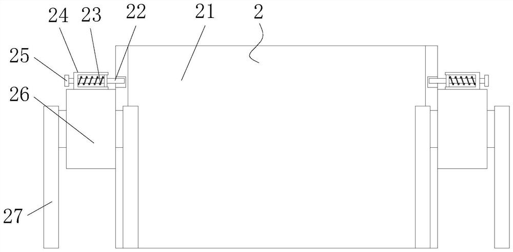
[0045] The difference between this embodiment and Embodiment 1 is: further; the bottom end of the plate and frame filter press 1 is provided with a mud cake take-out assembly 2, and the mud cake take-out assembly 2 includes a retrieving box 21, a limit insertion rod 22, a limit Position spring 23, fixed frame 24, pull handle 25, transmission belt 26, support frame 27 and guide device 28, wherein, the bottom end of plate and frame filter press 1 is symmetrically provided with support frame 27, and the upper end of support frame 27 is provided with transmission belt 26 , the surface of the transmission belt 26 is provided with a fixed frame 24, the interior of the fixed frame 24 is provided with a limit insertion rod 22, the surface of the limit insertion rod 22 is socketed with a limit spring 23, and one side of the limit insertion rod 22 is provided with a pull handle 25. A retrieving box 21 is arranged between the transmission belts 26, and guide devices 28 are provided on bot...


PUM


Abstract

The invention discloses a municipal sludge and engineering slurry co-processing device, and belongs to the technical field of sludge treatment. The municipal sludge and engineering slurry co-processing device comprises a ball mill, a plate-and-frame filter press is arranged on one side of the ball mill, and a convenient cooling assembly is arranged at the bottom end of the ball mill; the convenient cooling assembly comprises a collecting tank, a fiber filter screen, a flow guide pipe, a mounting frame, a water pump and a spraying pipe, the collecting tank is arranged at the bottom end of the ball mill, the fiber filter screen is arranged in the collecting tank, the mounting frame is arranged at the upper end of the collecting tank, and the water pump is arranged at the upper end of the mounting frame. A flow guide pipe is arranged at the bottom end of the water pump, and the spraying pipe is arranged at the upper end of the water pump; by arranging the convenient cooling assembly, the water pump pumps the cooling liquid to continuously cool the gear on the surface of the ball mill, so that the continuous working stability of the ball mill is ensured, the energy consumption is reduced, the working quality is improved, municipal sludge and engineering slurry can be fully mixed, and the use effect is improved.

Description

technical field [0001] The invention belongs to the technical field of sludge treatment, and in particular relates to a municipal sludge and engineering mud co-processing device and a co-processing method thereof. Background technique [0002] Municipal sludge is the residue of municipal sewage treatment, which has the characteristics of high water content (about 80%), viscous, difficult to dehydrate, and easy to rot and smell. Engineering mud refers to the mud-water mixture produced during construction, tunnel engineering, foundation engineering, etc. Its main components are clay and fine sand, with a moisture content of about 80-90%. It has good fluidity and is easy to dehydrate. Various flocculants still need to be added before. [0003] There are following problems in prior art: [0004] 1. The prior art mainly uses high-speed stirring to mix municipal sludge and engineering mud evenly in batches, and the operating efficiency is low. Moreover, because the municipal sl...

Claims


Application Information

Patent Timeline
Patent Type & Authority Applications(China)
IPC IPC(8): C02F11/00C02F11/122C02F11/143B01D25/21B01D25/30B01D37/02B02C17/10B02C17/18
CPCB01D25/21B01D37/02B01D25/30B02C17/1815B02C17/10B02C17/183C02F11/00C02F11/122C02F11/143
Inventor 齐继红韩洪波温金传曾龙云
Owner 金茂(深圳)生态科技有限公司
Learn More