Auxiliary scattering panel and its manufacturing method and display device

A manufacturing method and technology of a display device, which are applied in the directions of instruments, nonlinear optics, optics, etc., can solve the problems of inability to transmit signals to the transparent electrode layer 16 , the transparent electrode layer 16 is prone to breakage, and the display effect cannot be achieved, so as to reduce the breakage. risk, avoid undercut problems, and reduce production costs

Active Publication Date: 2022-07-01
KUSN INFOVISION OPTOELECTRONICS
View PDF6 Cites 0 Cited by
  • Summary
  • Abstract
  • Description
  • Claims
  • Application Information

AI Technical Summary

Problems solved by technology

[0005] Please refer to the next steps Figures 1g to 1h As shown, with the help of the planarization layer 15, the passivation layer 13 remaining outside the display area that is not covered by the planarization layer 15 is removed by a dry etching process, exposing the metal circuit layer 12. Due to the difference in the etch rate selectivity , the undercut phenomenon occurs in the passivation layer 13 (refer to the dotted line box 133 in the figure, the passivation layer 13 is indented to be located below the planarization layer 15), and then the entire transparent electrode layer 16 is fabricated on the planarization layer 15, The transparent electrode layer 16 covers the metal wiring layer 12 and the planarization layer 15 at the same time, but due to the undercut problem, the transparent electrode layer 16 is prone to breakage at the undercut position, such as Figure 1h As shown, the signal transmitted from the peripheral area cannot be transmitted to the transparent electrode layer 16 on the planarization layer 15, and thus the desired display effect cannot be achieved.
[0006] The existing technical problem solving method is: additionally design and purchase a mask (Msak), in the above Figure 1f Afterwards, the passivation layer 13 above the metal wiring layer 12 is removed by photolithography and dry etching (that is, the passivation layer 13 above the metal wiring layer 12 is no longer removed by the shielding of the planarization layer 15), but in this way It requires additional design and purchase of a mask, which increases the production cost

Method used


Image

  • Auxiliary scattering panel and its manufacturing method and display device
  • Auxiliary scattering panel and its manufacturing method and display device
  • Auxiliary scattering panel and its manufacturing method and display device

Examples


no. 1 example

[0052] The manufacturing method of the auxiliary scattering panel provided in the first embodiment of the present invention includes the following steps:

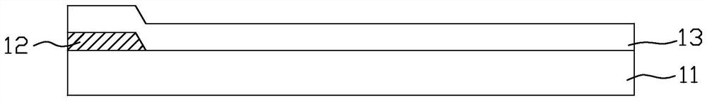
[0053] Please refer to Figure 3a , firstly provide the base substrate 21, and then form the metal circuit layer 22 on the base substrate 21. Specifically, the manufacture of the metal circuit layer 22 can be performed by first depositing a metal layer on the base substrate 21, and then forming the metal circuit layer 22 on the base substrate 21. A wet etching process is performed to form the metal circuit layer 22 , and the material of the metal circuit layer 22 may be a single-layer or multi-layer structure such as aluminum and molybdenum.

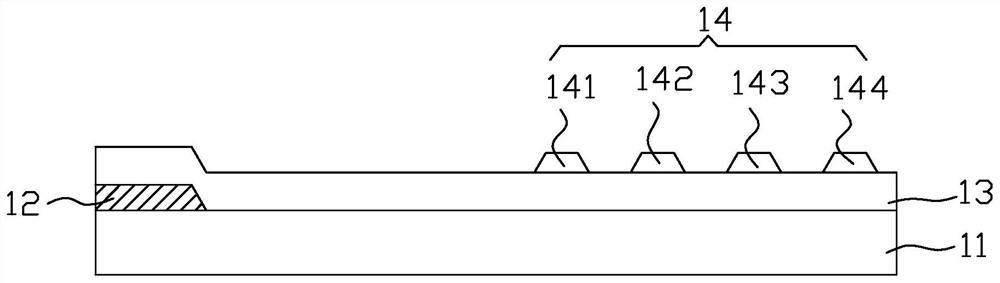
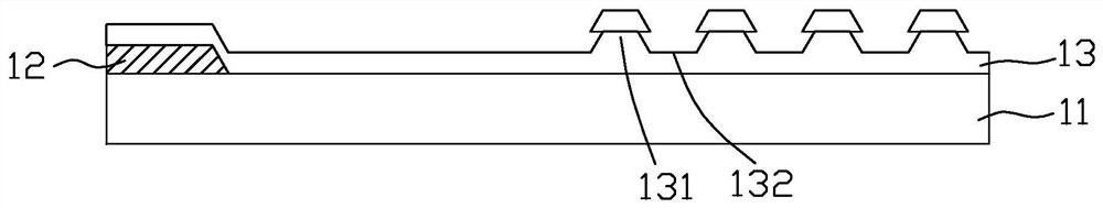
[0054] Please refer to Figure 3b , and then form a first passivation layer 23 on the metal circuit layer 22 and the base substrate 21 , and then use a mask to form a first photoresist layer 24 on the first passivation layer 23 . in:

[0055] The first passivation layer 23 covers t...

no. 2 example

[0066] Please refer to Figure 4a , the difference between the manufacturing method of the auxiliary scattering panel provided by the second embodiment of the present invention and the above-mentioned first embodiment is that after the planarization layer 25 is formed in the above-mentioned first embodiment (the manufacturing process before the planarization layer 25 is formed is different from that of the first embodiment) The embodiment is the same, and will not be repeated here), first, instead of forming the second photoresist layer 26 on the planarizing layer 25, a second passivation layer 28 is formed on the planarizing layer 25, and the second passivation layer 28 The exposed parts of the metal wiring layer 22 and the protrusions 232 are covered. The material of the second passivation layer 28 may be a single-layer or multi-layer structure such as silicon oxide, silicon nitride, silicon oxynitride, and aluminum oxide.

[0067] Please refer to Figure 4b , using the sa...


PUM


Abstract

An auxiliary scattering panel, a manufacturing method thereof, and a display device, the manufacturing method comprising the following steps: providing a base substrate; forming a metal circuit layer on the base substrate; forming a first passivation layer on the metal circuit layer and the base substrate; Using a mask, a first photoresist layer is made on the first passivation layer; the first passivation layer is etched for the first time to make a lens structure and a raised part; the first photoresist layer is peeled off; A planarization layer is formed on the first passivation layer; the first passivation layer is etched for a second time, the first passivation layer above the metal circuit layer is removed, and the raised part is still retained and exposed after the etching; A whole transparent electrode layer is deposited on the planarization layer, and the transparent electrode layer is laid along the planarization layer on the exposed protrusions, and then laid on the metal circuit layer and electrically connected with the metal circuit layer. The manufacturing method can avoid the problem of undercut, make the transparent electrode layer connect smoothly at the slope, and reduce the risk of rupture of the transparent electrode layer.

Description

technical field [0001] The present invention relates to the technical field of screen display, in particular to an auxiliary scattering panel used in conjunction with a display panel, a manufacturing method thereof, and a display device having the auxiliary scattering panel. Background technique [0002] Thin Film Transistor Liquid Crystal Display (TFT-LCD) can display high-definition, continuous and delicate images, and is increasingly favored by consumers. [0003] There is a new type of liquid crystal display technology, in which two liquid crystal cells are superimposed and used for display, one liquid crystal cell is a display panel, and the main function is to display the screen, and the other liquid crystal cell is an auxiliary scattering panel, which is provided with a lens structure, and its main function is diffuse light. By energizing the upper and lower electrodes in the scattering panel, a potential difference is formed to control the deflection of the liquid c...

Claims


Application Information

Patent Timeline
Patent Type & Authority Patents(China)
IPC IPC(8): G02F1/29G02F1/1343G02F1/1335G02F1/1347
CPCG02F1/29G02F1/134309G02F1/133526G02F1/1347G02F1/13476
Inventor 孙明剑李家琪
Owner KUSN INFOVISION OPTOELECTRONICS
Why Eureka
Try Eureka