Ultrasonic assisted abrasive machining method for tubular honeycomb curved surface of composite material

A composite material, ultrasonic-assisted technology, used in metal processing equipment, grinding/polishing equipment, grinders, etc. Solve the problems of bonding reliability of the assembly surface and the crushing of the composite material tube to achieve the effect of improving the material removal rate, suppressing the phenomenon of letting the knife, and reducing the wear of the tool.

Active Publication Date: 2021-07-27
DALIAN UNIV OF TECH
View PDF16 Cites 2 Cited by
  • Summary
  • Abstract
  • Description
  • Claims
  • Application Information

AI Technical Summary

Problems solved by technology

According to the patent documents with publication numbers CN201710808999.6 and CN201810157494.2, for composite materials and honeycomb structures, the processing method of high-speed milling is adopted. Since the in-plane rigidity of the composite tubular honeycomb is weak, it is very easy to The phenomenon of honeycomb deformation, composite material tube debonding, composite material tube crushing, and tube wall tearing will affect the structural integrity and surface accuracy of composite material tubular honeycomb; at the same time, the surface processed by high-speed milling composite material honeycomb will be damaged. Processing damage such as burrs and delamination will affect the bonding reliability of the array composite tube and skin bonding assembly surface
If the traditional grinding method is used instead of milling, the grinding produced by grinding will easily block the grinding wheel, resulting in a substantial increase in the heat generated by sliding and burning the machined surface

Method used


Image

  • Ultrasonic assisted abrasive machining method for tubular honeycomb curved surface of composite material
  • Ultrasonic assisted abrasive machining method for tubular honeycomb curved surface of composite material
  • Ultrasonic assisted abrasive machining method for tubular honeycomb curved surface of composite material

Examples


Embodiment Construction

[0032] In order to make the purpose, technical solutions and advantages of the embodiments of the present invention clearer, the technical solutions in the embodiments of the present invention will be clearly and completely described below in conjunction with the drawings in the embodiments of the present invention. Obviously, the described embodiments It is a part of embodiments of the present invention, but not all embodiments. Based on the embodiments of the present invention, all other embodiments obtained by persons of ordinary skill in the art without making creative efforts belong to the protection scope of the present invention.

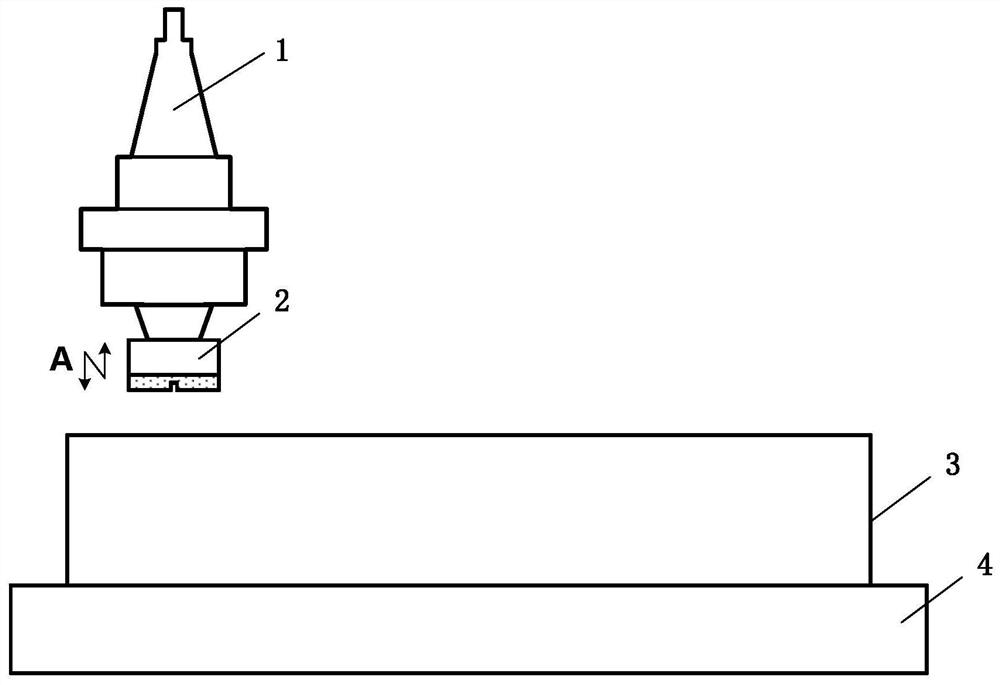
[0033] This embodiment discloses a method for ultrasonically assisted grinding of composite material tubular honeycomb components, including the following steps:

[0034] S1, such as figure 1 As shown, the composite tubular honeycomb 3 is fixed on the tooling 4, the cup-shaped grinding wheel 2 is installed on the ultrasonic tool holder 1, an...


PUM


Abstract

The invention discloses an ultrasonic assisted abrasive machining method for a tubular honeycomb curved surface of a composite material. The method comprises the following steps: fixing a tubular honeycomb of the composite material to a tool, mounting a cup-shaped grinding wheel to an ultrasonic knife handle and mounting the ultrasonic knife handle to a machine tool spindle; roughly machining the tubular honeycomb curved surface of the composite material along a tool path under an ultrasonic vibrating action to obtain a tubular honeycomb member of the composite material with a step shape; and using a ball grinding wheel alternately, mounting the ball grinding wheel to the ultrasonic knife handle, mounting the ultrasonic knife handle to the machine tool spindle, and finish machining the tubular honeycomb curved surface of the composite material along the tool path under the ultrasonic vibrating action, and removing the step and a residual working allowance to obtain the processed curved surface of the tubular honeycomb member of the composite material with high quality. By adopting the ultrasonic assisted abrasive machining method, it has the advantages of few machining damage, good machining quality, high machining precision and difficulty to plug the grinding wheel by abrasive dust. Low damage and high surface figure accuracy machining of the tubular honeycomb of the composite material can be realized.

Description

technical field [0001] The invention relates to the technical field of composite material tubular honeycomb processing, in particular to an ultrasonic-assisted grinding processing method for composite material tubular honeycomb curved surfaces. Background technique [0002] Traditional antenna reflector panels mostly use a sandwich structure of carbon fiber composite skin and aluminum honeycomb sandwich core, but the non-uniform thermal deformation of reflector panels with heterogeneous structures in extreme environments will lead to poor surface shape accuracy stability. The full carbon fiber reflective panel can solve the problem of non-uniform thermal deformation caused by the heterogeneous structure and meet the high-precision stability requirements of the antenna reflective panel. According to the patent document with the publication number CN201810813952.3, the full carbon fiber reflective panel can be divided into a grid structure reflective panel, a carbon honeycomb ...

Claims


Application Information

Patent Timeline
Patent Type & Authority Applications(China)
IPC IPC(8): B24B1/04B24B19/26
CPCB24B1/04B24B19/26
Inventor 康仁科董志刚郝宗成刘志强
Owner DALIAN UNIV OF TECH
Why Eureka
Try Eureka