Flue gas carbon dioxide trapping and purifying system and method

A carbon dioxide and flue gas technology, applied in liquefaction, refrigeration and liquefaction, climate sustainability, etc., can solve the problems of environmental pollution and high energy consumption by chemical absorption, improve energy utilization, reduce carbon capture energy consumption, The effect of improving energy efficiency

Pending Publication Date: 2021-07-27
HARBIN INST OF TECH
View PDF0 Cites 4 Cited by
  • Summary
  • Abstract
  • Description
  • Claims
  • Application Information

AI Technical Summary

Problems solved by technology

[0004] The purpose of the present invention is to solve the existing problems of high energy consumption in the physical separation method and environmental pollution in the chemical absorption method when capturing carbon dioxide in low-concentration flue gas, and provides a system and method for capturing and purifying carbon dioxide in flue gas

Method used


Image

  • Flue gas carbon dioxide trapping and purifying system and method
  • Flue gas carbon dioxide trapping and purifying system and method
  • Flue gas carbon dioxide trapping and purifying system and method

Examples


specific Embodiment approach 1

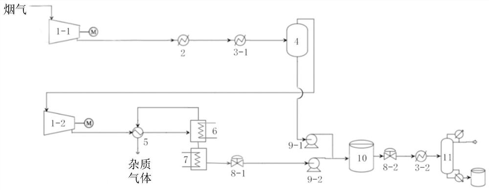
[0063] Specific implementation mode one: the following combination figure 1 Describe this embodiment, a flue gas carbon dioxide capture and purification system described in this embodiment includes a first air compressor 1-1, a second air compressor 1-2, a cold water heat exchanger group 2, a first refrigerant Heat exchanger 3-1, second refrigerant heat exchanger 3-2, carbon dioxide separator 4, gas heat exchanger 5, desublimator 6, sublimator 7, first pressure regulating valve 8-1, second regulator Pressure valve 8-2, first booster pump 9-1, second booster pump 9-2, carbon dioxide storage tank 10 and rectification tower 11;

[0064] The air inlet of the first air compressor 1-1 is used to receive flue gas;

[0065] The flue gas output by the first air compressor 1-1 is sent to the carbon dioxide Separator 4;

[0066] The carbon dioxide separator 4 is used to separate the carbon dioxide in the flue gas, and output the liquid carbon dioxide and the mixed gas;

[0067] The l...

specific Embodiment approach 2

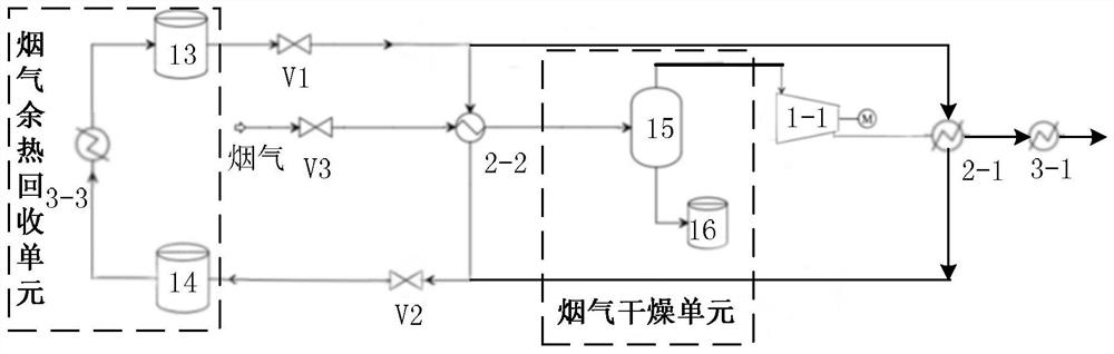
[0078] Specific implementation mode two: the following combination Figure 1 to Figure 3 To illustrate this embodiment, this embodiment will further describe a flue gas carbon dioxide capture and purification system described in Embodiment 1. The purification system also includes a flue gas waste heat recovery unit and a flue gas drying unit;

[0079] The flue gas drying unit is used to dry the flue gas before sending it to the first air compressor 1-1;

[0080] The flue gas waste heat recovery unit is used to pass cooling water into the cold water heat exchanger group 2 to cool down the flue gas, recover the waste heat of the flue gas through the cooling water, and recycle the cooling water after recovering the waste heat of the flue gas.

[0081] In this embodiment, drying the flue gas through the flue gas drying unit can recover most of the moisture in the flue gas for recycling, which is of great significance for the construction of generating units in water-scarce areas a...

specific Embodiment approach 3

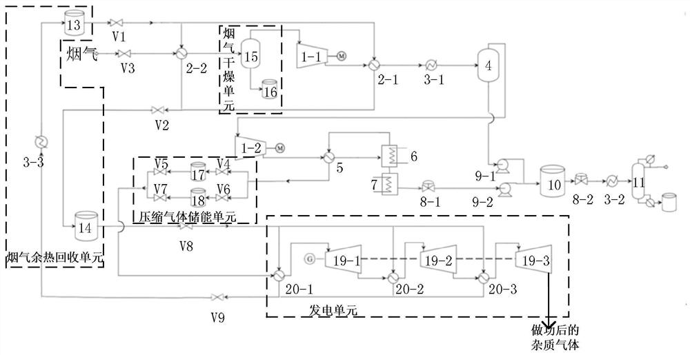
[0082] Specific implementation mode three: the following combination figure 2 and image 3 Describe this embodiment. This embodiment will further describe a flue gas carbon dioxide capture and purification system described in Embodiment 2. The cold water heat exchanger group 2 includes a first cold water heat exchanger 2-1 and a second cold water heat exchanger device 2-2;

[0083] The flue gas waste heat recovery unit includes a low-temperature water storage tank 13, a high-temperature water storage tank 14 and a third refrigerant heat exchanger 3-3;

[0084] The flue gas drying unit includes a gas-liquid separator 15 and a water storage tank 16;

[0085] The first cold water heat exchanger 2-1 is arranged on the pipeline between the first air compressor 1-1 and the first refrigerant heat exchanger 3-1;

[0086] The low-temperature water storage tank 13 is used to provide cooling water for the first cold water heat exchanger 2-1 and the first cold water heat exchanger 2-2...


PUM


Abstract

The invention discloses a flue gas carbon dioxide trapping and purifying system and method, and relates to the field of flue gas pollutant purification treatment. The problems that when carbon dioxide in low-concentration flue gas is captured in the prior art, energy consumption is high when a physical separation method is adopted, and environmental pollution exists when a chemical absorption method is adopted are solved. After flue gas is cooled twice through a cold water heat exchanger set and a second refrigerant heat exchanger in sequence, low-temperature physical separation of carbon dioxide is conducted on low-concentration carbon dioxide flue gas through a carbon dioxide separator, liquid carbon dioxide and mixed gas are separated out, residual carbon dioxide gas in the mixed gas is further purified, and therefore, the purification of the low-concentration carbon dioxide flue gas is realized. The flue gas carbon dioxide trapping and purifying system and method is mainly used for purifying flue gas pollutants.

Description

technical field [0001] The invention relates to the field of flue gas pollutant purification treatment. Background technique [0002] Carbon dioxide is the main gas that causes environmental problems such as the greenhouse effect. It mainly comes from the burning of fossil fuels in industrial production. With the frequent occurrence of global climate problems, countries around the world have put forward stricter requirements for carbon dioxide emissions. Carbon capture technology is It is currently the most direct method to control carbon dioxide emissions, and can realize large-scale industrial application. [0003] At present, the most commonly used carbon dioxide capture method is chemical absorption method, but for carbon capture in low-concentration carbon dioxide flue gas, chemical absorption method has problems such as large capture equipment and high regeneration energy consumption. In addition, the use of chemical reagents will affect the Environmental impact; and ...

Claims


Application Information

Patent Timeline
Patent Type & Authority Applications(China)
IPC IPC(8): F23J15/06F25J3/02F25J3/08
CPCF23J15/06F25J3/0266F25J3/08F25J3/067F25J2205/20F25J2210/70F25J2230/04F25J2230/30F25J2240/90F25J2260/02F25J2270/90F25J2290/62Y02E20/30Y02C20/40
Inventor 孙锐王兴益杜谦孟晓晓
Owner HARBIN INST OF TECH
Why Eureka
Try Eureka