
Tunable inductance device based on inverse magnetoelectric effect

A technology of tuning inductance and electric effect, applied in the direction of continuously variable inductor/transformer, transformer/inductor magnetic core, etc., to achieve high integration, reduce magnetic leakage, and improve adjustability

Inactive Publication Date: 2021-07-27
NANJING UNIV OF SCI & TECH
View PDF6 Cites 0 Cited by
  • Summary
  • Abstract
  • Description
  • Claims
  • Application Information

AI Technical Summary

Problems solved by technology

In microwave devices, magnetoelectric materials can be used to make signal processing devices such as resonators, attenuators, phase shifters, delay lines and filters. It needs a small amount of energy to work, and the device can be miniaturized, but there are still few studies on the application of magnetoelectric composite materials to the field of inductors.

Method used


Image

  • Tunable inductance device based on inverse magnetoelectric effect
  • Tunable inductance device based on inverse magnetoelectric effect
  • Tunable inductance device based on inverse magnetoelectric effect

Examples


Embodiment 1

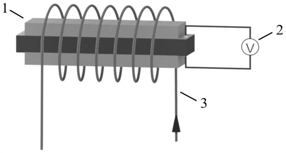
[0025] Such as figure 1 As shown, a tunable inductance device based on the reverse magnetoelectric effect includes an adjustable magnetic core 1, a controllable voltage source 2 and a winding 3, the adjustable magnetic core 1 is connected to the controllable voltage source 2, and the adjustable magnetic core 1 A single-layer winding 3 is arranged on the periphery, and both ends of the winding 3 are connected with alternating current.

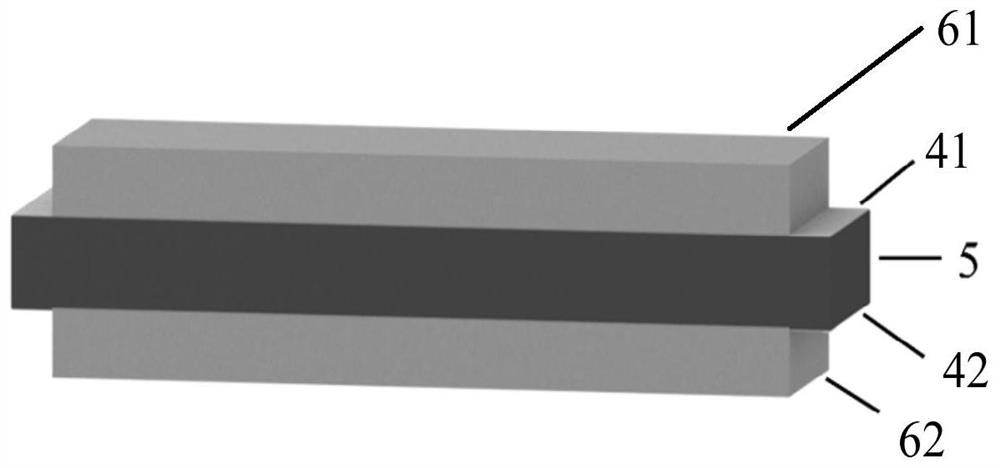
[0026] Such as figure 2 As shown, the adjustable magnetic core 1 is a strip-shaped magnetoelectric heterojunction with a sandwich structure, including a first magnetostrictive layer 61, a first piezoelectric structure, and a second magnetostrictive layer 62 stacked in sequence. The electrical structure includes a first electrode 41 , a piezoelectric layer 5 and a second electrode 42 stacked in sequence. The first electrode 41 and the second electrode 42 are partly exposed and connected to two ends of the controllable voltage source 2 respectiv...

Embodiment 2

[0035] Such as Figure 5 As shown, a tunable inductance device based on the reverse magnetoelectric effect includes an adjustable magnetic core 1, a controllable voltage source 2 and a winding 3, the adjustable magnetic core 1 is connected to the controllable voltage source 2, and the adjustable magnetic core 1 A single-layer winding 3 is arranged on the periphery, and both ends of the winding 3 are connected with alternating current.

[0036] Such as Figure 6 As shown, the adjustable magnetic core 1 is a zigzag magnetoelectric heterojunction with a sandwich structure, including a first magnetostrictive layer 63, a second piezoelectric structure, and a second magnetostrictive layer 64 stacked in sequence. The shapes of the stretchable layers are all back-shaped, and the second piezoelectric structure is a back-shaped structure composed of four first piezoelectric structures spliced ​​together. The first electrode 41 and the second electrode 42 are partially exposed, and are ...


PUM

PropertyMeasurementUnit
Sensitivityaaaaaaaaaa

Abstract

The invention discloses a tunable inductance device based on the inverse magnetoelectric effect, and relates to the field of electronic components, the device comprises an adjustable magnetic core, a controllable voltage source and a winding, the adjustable magnetic core is a magnetoelectric heterojunction of a sandwich structure and is connected with the controllable voltage source through a wire, and the winding connected with alternating current is arranged on the periphery of the adjustable magnetic core; the magnetoelectric heterojunction is based on a magnetoelectric coupling effect, and can realize electricity-machine-magnetism conversion. By means of the inverse magnetoelectric effect, the inductance is regulated and controlled by changing the voltage of the controllable voltage source, and the device has the advantages of being low in energy consumption, small in size, large in adjustability and capable of being continuously adjusted and has important application prospects in the integrated, miniaturized and multifunctional electronic field in the future.

Description

technical field [0001] The invention relates to the field of electronic components, in particular to a tunable inductance device based on the reverse magnetoelectric effect. Background technique [0002] As the most basic circuit element, inductors are indispensable in important fields such as communication and electronics, and have functions such as voltage regulation, filtering, and oscillation. For a long time, the multi-functionalization, integration and miniaturization of devices are the urgent needs of the development of science and technology. Tunable inductors are expected to replace numerous inductors and capacitors in the circuit, thereby reducing the number of circuit components and promoting the development of device miniaturization. For example, conventional point-of-load converters require high-performance inductors and large output capacitors in order to achieve high efficiency, high power density, and low noise. The point-of-load converter based on adjustab...

Claims


Application Information

Patent Timeline
Patent Type & Authority Applications(China)
IPC IPC(8): H01F21/08H01F27/24
CPCH01F21/08H01F27/24
Inventor 汪尧进聂长文宋树蔡园园李娣洁潘韩
Owner NANJING UNIV OF SCI & TECH
Learn More