
Petroleum drilling mud and solid waste separating and recycling device

A technology for solid waste and oil drilling, applied in filtration separation, separation method, transportation and packaging, etc., can solve the problems of inconvenient lime mixing, increased mixing difficulty, high maintenance cost, etc., to avoid frequent transshipment, reduce dehydration treatment cost, Guaranteed effect of mixing effects

Active Publication Date: 2021-07-30
榆林昌荣华城再生能源有限公司
View PDF12 Cites 0 Cited by
  • Summary
  • Abstract
  • Description
  • Claims
  • Application Information

AI Technical Summary

Problems solved by technology

[0005] In order to overcome the need to separate the mud discharged from the wellbore from the solid waste, the solid waste is collected and sent for dehydration treatment. The dehydrated solid waste is sent to the land building material sintering plant for waste utilization, and the separated mud is collected Afterwards, it is mixed with lime for the paving of roads at oil well sites. This treatment method has many steps and requires continuous transshipment of waste. Moreover, the surface of the mud is easy to condense after being collected and stored, which is inconvenient to mix with lime, which increases the difficulty of mixing. However, due to the high cost of operation and maintenance of the usual dehydration treatment machines, the technical problem to be solved is to provide a separation and reuse device for oil drilling mud and solid waste

Method used


Image

  • Petroleum drilling mud and solid waste separating and recycling device
  • Petroleum drilling mud and solid waste separating and recycling device
  • Petroleum drilling mud and solid waste separating and recycling device

Examples


Embodiment 1

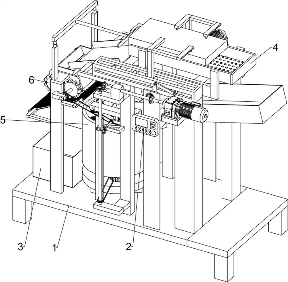
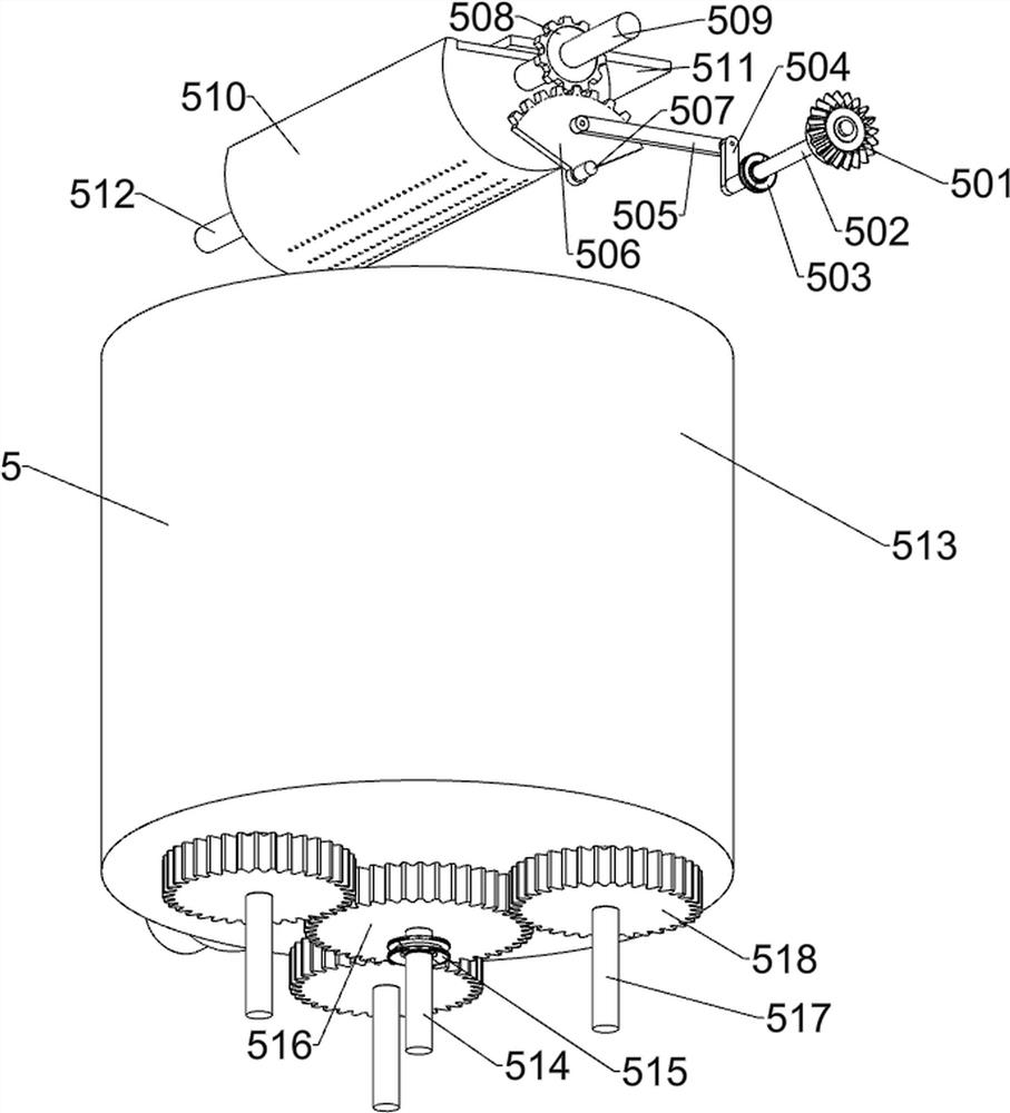
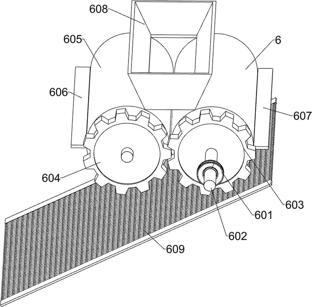
[0027] A device for separating and reusing oil drilling mud and solid waste, such as Figure 1-7 As shown, it includes an underframe 1, a controller 2, a waste water collection tank 3, a mud filter assembly 4, a mixing assembly 5 and a dehydration assembly 6; the underframe 1 is connected to the controller 2; the underframe 1 is connected to the waste water collection box 3 Connection; bottom frame 1 is connected with mud filter assembly 4; bottom frame 1 is connected with mixing assembly 5; bottom frame 1 is connected with dehydration assembly 6; mud filter assembly 4 is connected with mixing assembly 5; mixing assembly 5 is connected with dehydration assembly 6 phase connection.

[0028] When preparing for work, place the device on a horizontal surface, turn on the power supply, and transport the mixture of mud and solid waste to the mud filter assembly 4 on the chassis 1 through the existing technology, and control the mud filter assembly 4 through the controller 2. The mu...


PUM


Abstract

The invention relates to the technical field of petroleum drilling platforms, in particular to a petroleum drilling mud and solid waste separating and recycling device. The technical problem to be solved by the invention is to provide the petroleum drilling mud and solid waste separating and recycling device. According to the technical scheme, the petroleum drilling mud and solid waste separating and recycling device comprises a bottom frame, a controller, a waste water collecting box, a mud filtering assembly, a mixing assembly and a dewatering assembly, and the mixing assembly is connected with a dewatering assembly. When the device is used, slurry and solid waste are separated, after separation, the slurry is collected and mixed with lime at the same time, the mixing time is indirectly shortened while the mixing effect is guaranteed, meanwhile, the separated solid waste is dewatered through simple operation, the condition that the waste needs to be frequently transferred during treatment is avoided, and meanwhile, the dehydration treatment cost is reduced.

Description

technical field [0001] The invention relates to the technical field of an oil drilling platform, in particular to an oil drilling mud and solid waste separation and reuse device. Background technique [0002] Drilling is a project that uses mechanical equipment and related technologies to drill the stratum into cylindrical holes with a certain depth from the surface to the ground. Oil drilling is a drilling project for the purpose of discovering oil, natural gas and other hydrocarbons. Drilling is a It is a high-pollution industry, and the main sources of pollution are waste mud and solid waste. The continuous discharge of waste drilling mud not only costs a lot, but also causes serious pollution to the environment if it is not treated in a timely and effective manner. [0003] In the existing technology, it is necessary to separate the mud discharged from the wellbore from the solid waste, collect the solid waste and send it to dehydration treatment, and send the dehydrated...

Claims


Application Information

Patent Timeline
Patent Type & Authority Applications(China)
IPC IPC(8): B01F7/16B01F7/24B01F3/20B01F15/02C02F11/00C02F11/121B01D29/03B01D33/01B01D36/02B01F23/70
CPCC02F11/121C02F11/00B01D33/0158B01D29/03B01D36/02B01F23/70B01F23/708B01F27/85B01F27/922B01F35/712B01F35/71
Inventor 许俊超
Owner 榆林昌荣华城再生能源有限公司
Learn More