Thermal desorption remediation device for polluted soil

A thermal desorption technology for contaminated soil, applied in the field of thermal desorption repair devices, can solve the problems of waste of heat energy, affecting the effect of thermal desorption, short contact time, etc.

Active Publication Date: 2021-07-30
SHANXI NO 8 CONSTR GRP
View PDF20 Cites 1 Cited by
  • Summary
  • Abstract
  • Description
  • Claims
  • Application Information

AI Technical Summary

Problems solved by technology

[0004] In order to solve the problem that the existing restoration device has a short contact time with the soil, which affects the effect of thermal desorption, and at the same time, the soil is easy to agglomerate, which makes the heating speed slow and causes waste of heat energy, and provides a thermal desorption restoration device for polluted soil. Meet actual use needs

Method used


Image

  • Thermal desorption remediation device for polluted soil
  • Thermal desorption remediation device for polluted soil
  • Thermal desorption remediation device for polluted soil

Examples


Embodiment

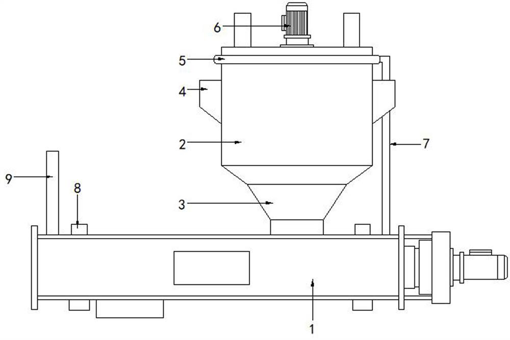
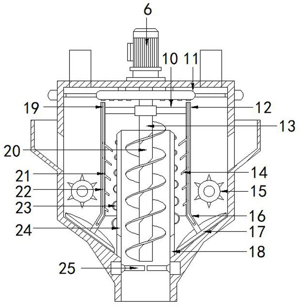
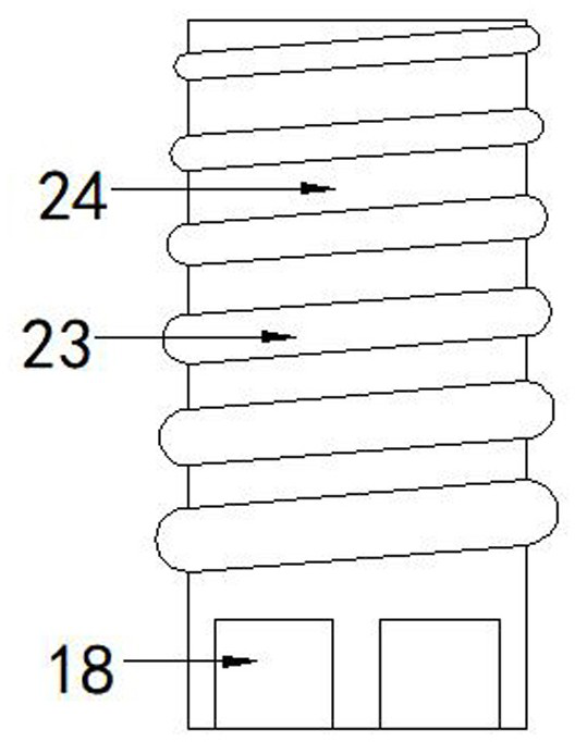
[0022] Such as figure 1 As shown, a thermal desorption restoration device for polluted soil includes a treatment device 2 connected in sequence from top to bottom and the internal cavity is communicated, a feed pipe 3 and a screw conveyor 1, and the screw conveyor The machine 1 and the feed pipe 3 are located on the top side of the screw conveyor 1; as figure 2 As shown, in the middle of the inner bottom of the processing device 2, a fixed pipe 24 with the same inner diameter as the feed pipe 3 is installed, and the lower end side wall of the fixed pipe 24 offers a feed guide hole 18, and the outer cover of the fixed pipe 24 A moving tube 12 is provided, and a transmission column 13 is also installed vertically inside the processing device 2. The end of the transmission column 13 extends into the fixed tube 24 and a spiral blade 20 is installed on the outer wall. The transmission column 13, the fixed tube 24 is coaxial with the moving tube 12, and the surface of the transmis...


PUM


Abstract

The invention relates to the technical field of soil treatment, in particular to a thermal desorption remediation device for polluted soil. The device comprises a treatment device, a material guide pipe and a spiral conveyor which are sequentially connected together from top to bottom, inner cavities of the treatment device, the material guide pipe and the spiral conveyor are communicated, and the spiral conveyor and the material guide pipe are located on one side of the top of the spiral conveyor; and a fixed pipe with the same inner diameter as the material guide pipe is installed in the middle of the inner bottom of the treatment device, the fixed pipe is sleeved with a movable pipe, a transmission column is further vertically installed in the treatment device, the tail end of the transmission column extends into the fixed pipe, and spiral blades are installed on the outer wall of the transmission column. The retention time of soil between the movable pipe and the fixed pipe is prolonged through a guide plate and a buffer strip, the heating efficiency is improved, the treated soil enters the spiral conveyor through the material guide pipe to be conveyed, the treated soil makes contact with inlet air in the reverse convection direction in the conveying process, secondary thermal desorption is conducted, the contact time between the soil and hot air is prolonged, and through two times of thermal desorption, the thermal desorption efficiency is improved.

Description

technical field [0001] The invention relates to the technical field of soil treatment, in particular to a thermal desorption restoration device for polluted soil. Background technique [0002] Soil remediation is a technical measure to restore contaminated soil to normal functions. In the soil remediation industry, there are more than one hundred existing soil remediation technologies, and there are more than ten commonly used technologies, which can be roughly divided into three types: physical, chemical and biological. The method, thermal desorption, refers to the process of volatilizing and separating organic pollutants and metal mercury in polluted soil through direct or indirect heat exchange, and effectively collecting and treating the volatilized pollutants. . As a non-combustion technology, thermal desorption has a wide range of pollutant treatment, removable equipment, and reusable soil after restoration. Especially for chlorine-containing organic compounds, non-ox...

Claims


Application Information

Patent Timeline
Patent Type & Authority Applications(China)
IPC IPC(8): B09C1/06B02C4/00B02C4/28
CPCB09C1/06B02C4/00B02C4/28
Inventor 宋磊王晔辉周强
Owner SHANXI NO 8 CONSTR GRP
Why Eureka
Try Eureka