Craniotomy device and method for brain surgery

A brain surgery, craniotomy device technology, applied in the direction of surgery, medical science, etc., can solve the problems of difficult drilling process, difficult centering, stuck drill, etc., to achieve the drilling process is simple, smooth and easy to operate, which is conducive to rapid recovery , to ensure the effect of the wound

A brain surgery, craniotomy device technology, applied in the direction of surgery, medical science, etc., can solve the problems of difficult drilling process, difficult centering, stuck drill, etc., to achieve the drilling process is simple, smooth and easy to operate, which is conducive to rapid recovery , to ensure the effect of the wound

CN113197615BActive Publication Date: 2022-03-08无锡市太湖医院

Image

  • Craniotomy device and method for brain surgery
  • Craniotomy device and method for brain surgery
  • Craniotomy device and method for brain surgery

Examples


Embodiment 1

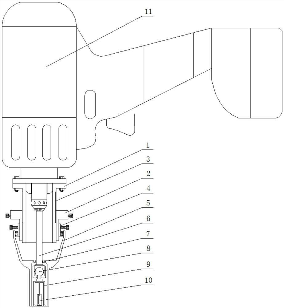
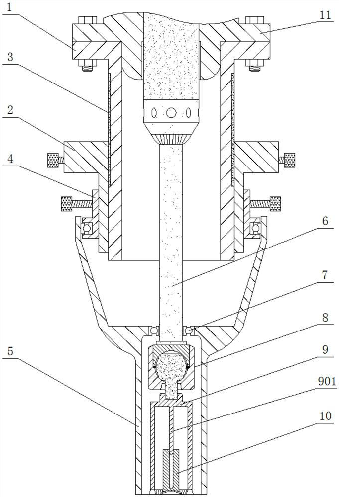
[0047] Refer to attached Figure 4 As shown, press one end of the suction cup at the lower part of the suction seat 10 against the skull surface, and ensure that the center of the suction seat 10 is concentrically aligned with the center of the hole to be drilled. Rotate the adjustment hoop 2 on the adjustment sleeve 1 to the zero scale position of the scale 3, then insert the centering sliding post 901 of the drill set 9 into the suction seat 10 and place the ring-shaped teeth 902 on the skull surface, at the same time The lower end of the righting limit sleeve 5 is placed on the skull surface, and the sliding sleeve 4 and the adjustment hoop 2 are screwed in and locked through the screws on the side.

Embodiment 2

[0049] Refer to attached Figure 5 As shown, on the basis of the steps in Embodiment 1, with reference to the thickness of the skull in the operation position, the righting limit sleeve 5 is adjusted upward through the adjustment hoop 2, so that the value of the adjustment hoop 2 on the scale 3 is equal to the thickness value of the skull in the operation position or It is 0 to 0.3 mm larger than the thickness value of the skull in the operation position. After adjustment, the adjustment hoop 2 and the adjustment sleeve 1 are locked through the screws on the side.

Embodiment 3

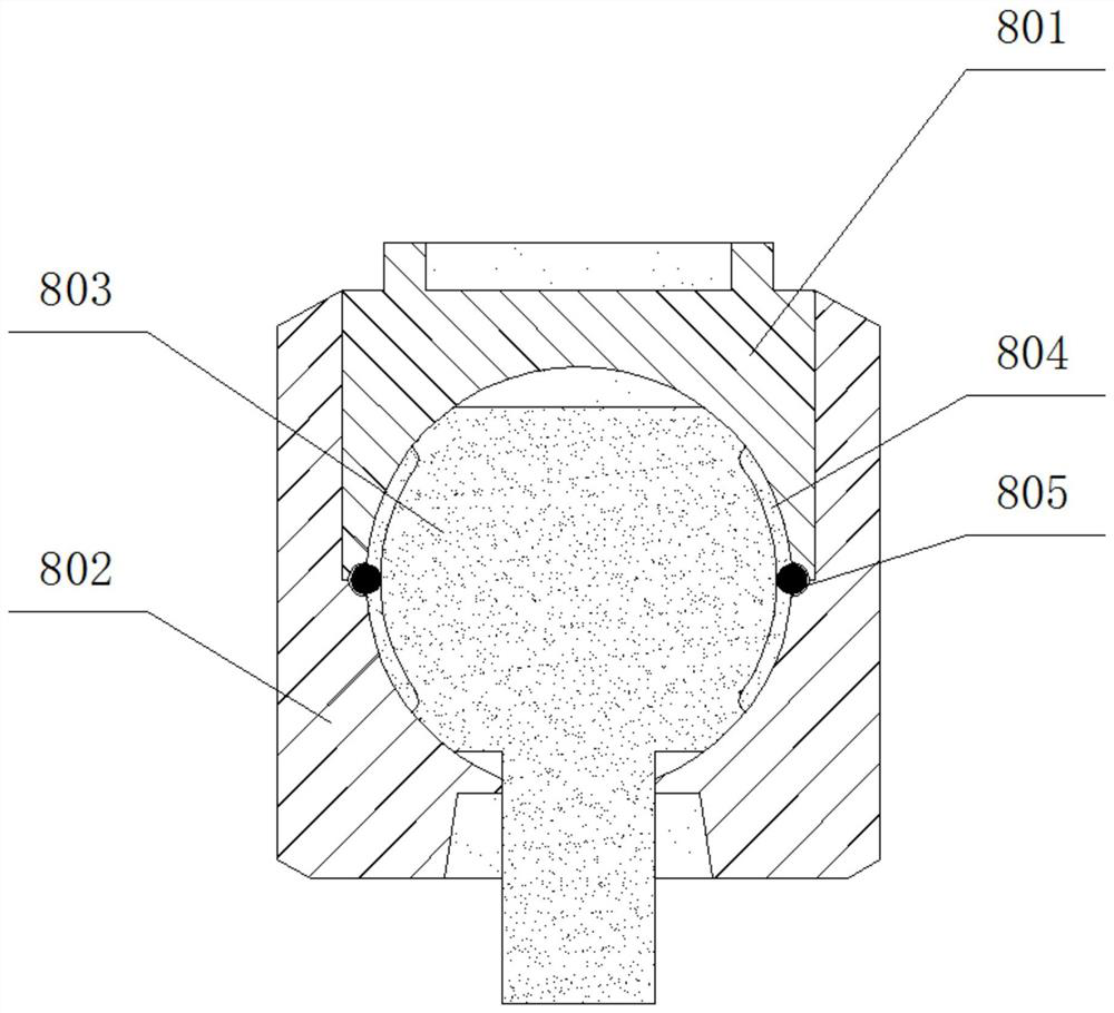
[0051] When drilling, manually press the switch of the drill body 11 to start the casing drill 9 to rotate, and the casing drill 9 digs out the hole through the annular tooth 902. The annular tooth 902 otch is annular and thinner, and the trauma is less, and the hole can be retained simultaneously. The circular bone flap has a small contact surface between the annular teeth 902 and the skull, and the set drill 9 can be closely fitted to the surface of the skull through the universal leveling handle 8 to ensure that all the annular teeth 902 are in contact with the skull surface. Uniform contact, the vibration force is extremely small when drilling, and the casing drill 9 can still be in uniform contact with the removed drill surface when the hole is drilled quickly, and the skull hole can be drilled smoothly, and the drill surface of the hole wall is uniform Excellent, there will be no stuck drill, and the drilling process is extremely simple, smooth and easy to operate. The n...


PUM


Abstract

The invention provides a craniotomy device and method for brain surgery, comprising: a positioning sleeve, the positioning sleeve is provided with an adjusting hoop that is threadedly matched with the adjusting hoop, and a There is a scale, and a sliding sleeve with a clearance fit is provided outside the adjusting hoop, and a righting limit sleeve that is rotationally connected is provided at the lower part of the sliding sleeve, and a drill pipe is arranged inside the righting limit sleeve, and a universal leveling joint is provided at the lower end of the drill pipe in turn And the casing drill, the casing drill is provided with a suction seat. In the present invention, the contact surface between the strip-shaped annular teeth and the skull is small, and the fit with the skull surface is good, so that all the annular teeth are in uniform contact with the skull surface, and the vibration force is extremely small during drilling, which can smoothly The skull hole is drilled through, and the phenomenon of drill sticking will not occur, and the drilling process is relatively simple and smooth; at the same time, the righting limit sleeve drill will not invade the meninges, the difficulty of drilling on the skull is extremely low, and the drilling process is simpler easy to operate.

Description

technical field [0001] The invention relates to a craniotomy device and method for brain surgery. Background technique [0002] The brain is the most fragile organ of the human body. The skull surrounds the brain to form a hard protective barrier. The brain has hundreds of millions of neurons, and the communication between neurons relies on long axons to transmit information. During intracranial craniotomy, the cut scalp is rolled up to one side to expose the skull. After determining the position of the skull cut, three holes are drilled in the skull, and the three holes are distributed in a triangle. The space is cut step by step with a scalpel, so that a triangular bone flap is cut off from the skull to realize the opening of the skull. The arcs formed by the three holes form a good transition to the corners of the triangle at the three corners of the triangular bone flap, which is convenient for stress relief. [0003] In today's craniotomy, the drilling of the skull is...

Claims


Application Information

Patent Timeline
08 Mar 2022
Publication
CN113197615B
IPC
A61B17/16
CPC
A61B17/1615; A61B17/162; A61B17/1624; A61B17/1626; A61B17/1631; A61B17/1633; A61B17/1695
Inventors
陈涛; 杨理坤