
A filling and caving mining method

A technology of caving mining and sub-caving method, which is applied in the fields of filling, ground mining, mining equipment, etc., can solve the problems such as mixing of gravel and tailings into ore drawing, large ore loss and dilution, and deterioration of ore drawing effect, etc. The effect of low loss and dilution, high mining intensity, and no surface subsidence

Active Publication Date: 2022-04-15
ANSTEEL GRP MINING CO LTD
View PDF3 Cites 0 Cited by
  • Summary
  • Abstract
  • Description
  • Claims
  • Application Information

AI Technical Summary

Problems solved by technology

[0015] In addition, since the top of the goaf is filled with waste rocks and beneficiation tailings to maintain the stability of the ground pressure, new problems have been brought about. Since the ore body below is mined by the sub-level caving method without bottom pillars, during the ore drawing process, the top filling The dry waste rock and beneficiation tailings are easily mixed into the ore drawing, especially the beneficiation tailings, the particles are very fine, resulting in a large amount of tailings passing through the newly collapsed ore and mixed into the released ore, which deteriorates the ore drawing effect
[0016] To sum up, in order to solve the problems of large ore loss and surface subsidence in the step-by-step caving method without pillars, overburden rock grouting and filling the goaf with filling wells at the top of the goaf can be used respectively, but the overburden rock must be resolved. The grouting problem of long-distance position change in the closed area, the problem of filling and connecting the top of the goaf, and the problem of serious ore dilution caused by the mixing of gravel and tailings from the top filling into the ore drawing

Method used


Image

  • A filling and caving mining method
  • A filling and caving mining method
  • A filling and caving mining method

Examples


Embodiment Construction

[0053] The specific implementation manner of the present invention will be further described below in conjunction with the accompanying drawings.

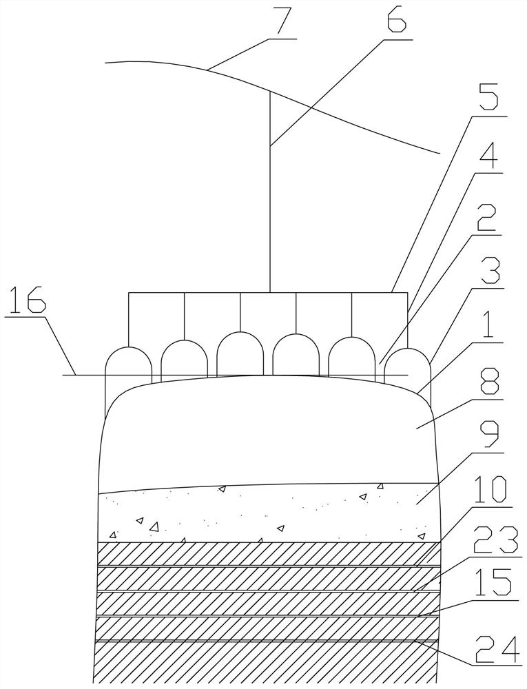
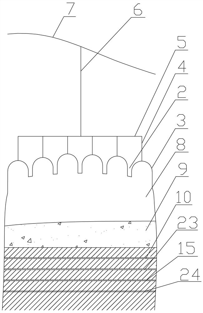
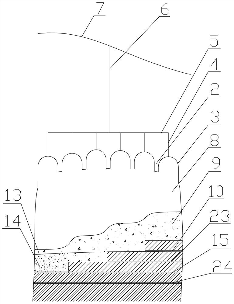
[0054] Such as figure 1 with figure 2 As shown, a filling and caving mining method of the present invention is characterized in that the ore is mined by subsection caving method without bottom pillars under the grouting cover rock layer 14, and arched suspension beams are constructed on the roof of the goaf, and the filling is carried out at the top. Concentrated filling of the goaf in the blind chute, the specific steps are as follows:

[0055] Step 1: Construct the arched suspension beam on the goaf roof and arrange the filling system

[0056] Adopt the blasting method to blast the roof 1 of the goaf 8 formed by the stepwise caving method without bottom pillars to form several arched suspension beam structures, and the arched suspension beams are composed of arches 3 and vertical beams 2; A number of filling blind chutes 4 co...


PUM


Abstract

The invention relates to a filling and caving mining method, which overcomes the new problems of large ore loss and depletion in the sub-section caving method without bottom pillars and surface subsidence and ore depletion caused by filling dry gravel and tailings at the top. The grouting method forms a layer of grouted overburden rock with a thickness reaching the height of two sections of the sub-pillar caving method in the overburden rock of the non-pillar segmental caving method, and carries out mining by the non-pillar segmental caving method under the grouted overburden rock Ore, so that the grouted overburden rock completely wraps the newly collapsed ore, prevents the front waste rock from being mixed in during the ore drawing process, and at the same time prevents the top-filled tailings from directly passing through the ore and mixing into the ore. In addition, an arched suspension beam is constructed on the roof of the goaf, and the goaf is centrally filled by filling the blind chute at the top, which has the advantages of simple mining process structure, high mining intensity, high efficiency, high degree of mechanization, safety, low mining cost, and smooth surface. Subsidence, low ore loss and dilution, etc., are suitable for underground mining of all metal ores.

Description

technical field [0001] The invention belongs to the technical field of filling and mining in underground mines, and relates to a filling and caving mining method. Background technique [0002] Underground mining methods include three basic processes of mining, cutting and back mining, and are divided into three categories according to the method of ground pressure maintenance: open-field mining method, filling mining method and caving mining method. [0003] Under the current environmental protection requirements, mines are recommended to use the filling method. For example, the traditional empty field method requires subsequent filling to prevent surface subsidence. However, the backfill mining method is mining in a large exposed area, which has poor safety, complicated filling process, and requires processes such as water filtration and cementation maintenance. The production capacity is small, and there are also disadvantages of high cost. [0004] As a representative o...

Claims


Application Information

Patent Timeline
Patent Type & Authority Patents(China)
IPC IPC(8): E21C41/22E21F15/00E21D11/10E21D11/18
CPCE21C41/22E21F15/005E21F15/00E21D11/10E21D11/18
Inventor 邵安林宫国慧马东胡世超李宗武张健王一淳
Owner ANSTEEL GRP MINING CO LTD
Learn More