
Transient milling temperature testing device capable of following cutter-cutting contact abrasion

A contact wear and testing device technology, applied in milling machine equipment, milling machine equipment details, measuring/indicating equipment, etc., can solve problems such as inability to obtain accurate temperature, sensor damage, etc., and achieve long life, fast dynamic response, and high sensitivity. Effect

Pending Publication Date: 2021-08-06
DALIAN JIAOTONG UNIVERSITY
View PDF0 Cites 0 Cited by
  • Summary
  • Abstract
  • Description
  • Claims
  • Application Information

AI Technical Summary

Problems solved by technology

[0003] Since the workpiece is fixed, the tool is rotated, and the blade is cutting intermittently during the milling process, the non-contact temperature measurement method cannot obtain the accurate temperature of the contact area between the rake face of the blade and the chip during processing, and the traditional contact temperature measurement method is easy. Sensor damage due to unavoidable friction

Method used


Image

  • Transient milling temperature testing device capable of following cutter-cutting contact abrasion
  • Transient milling temperature testing device capable of following cutter-cutting contact abrasion
  • Transient milling temperature testing device capable of following cutter-cutting contact abrasion

Examples


Embodiment Construction

[0029] It should be noted that, in the case of no conflict, the embodiments of the present invention and the features in the embodiments can be combined with each other. The present invention will be described in detail below with reference to the accompanying drawings and examples.

[0030] In order to make the purpose, technical solutions and advantages of the embodiments of the present invention clearer, the technical solutions in the embodiments of the present invention will be clearly and completely described below in conjunction with the drawings in the embodiments of the present invention. Obviously, the described embodiments It is only some embodiments of the present invention, but not all embodiments. The following description of at least one exemplary embodiment is merely illustrative in nature and in no way taken as limiting the invention, its application or uses. Based on the embodiments of the present invention, all other embodiments obtained by persons of ordina...


PUM


Abstract

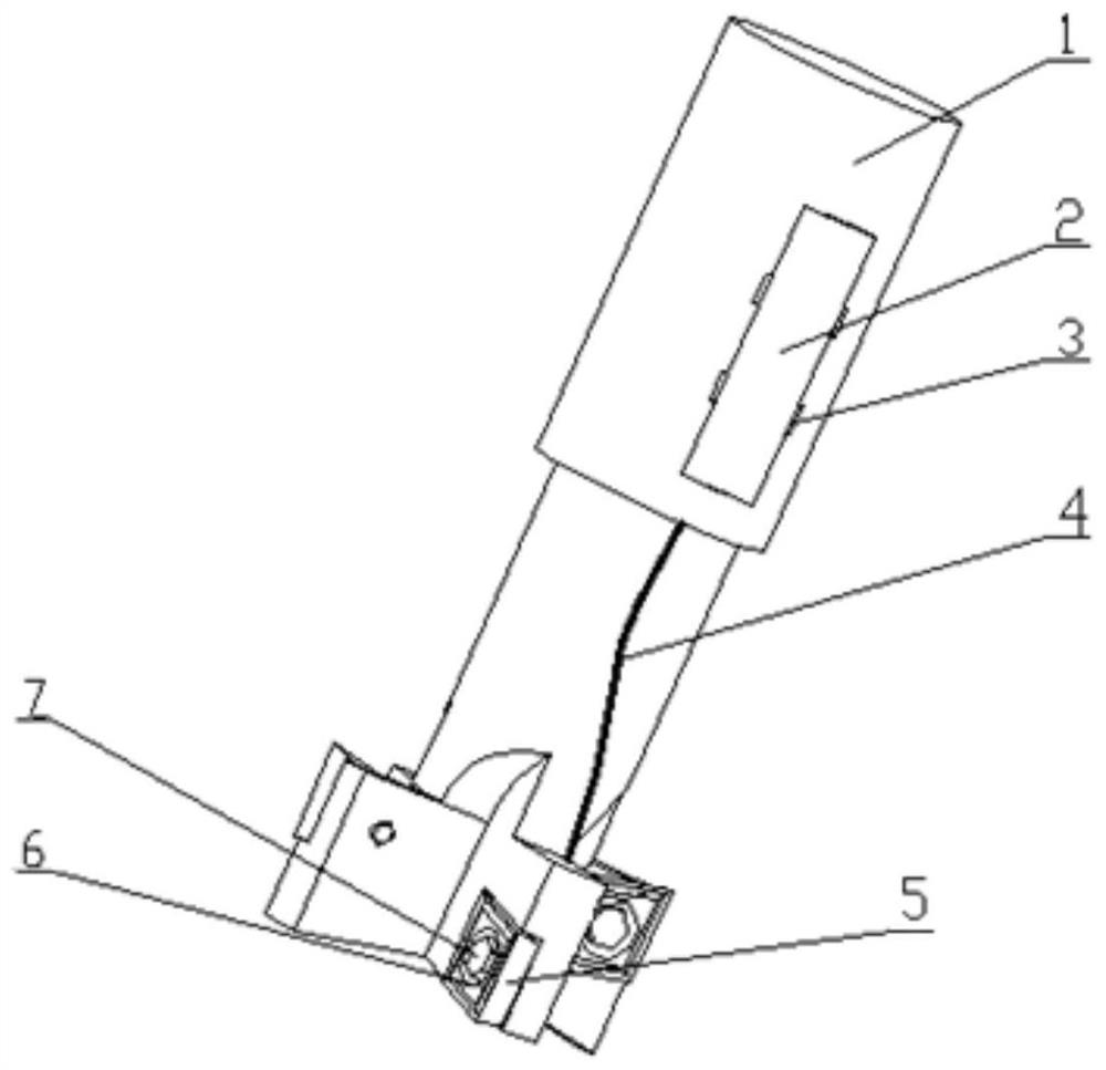
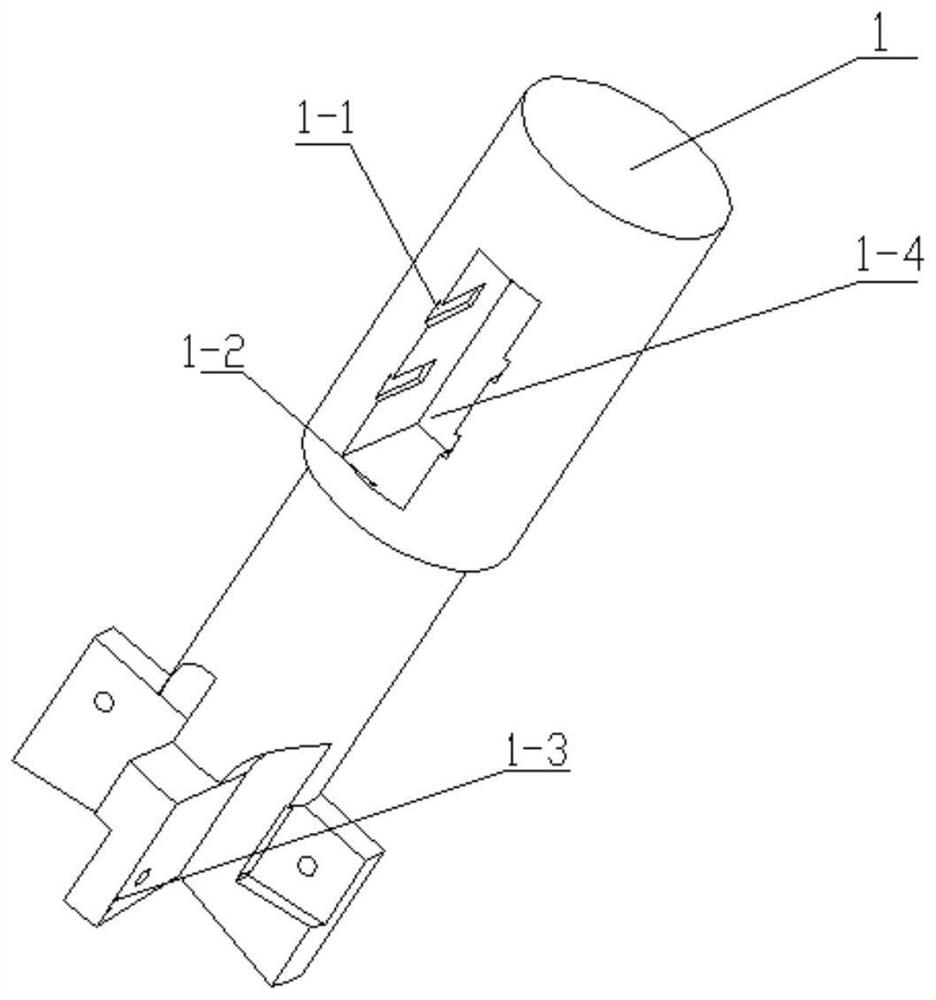
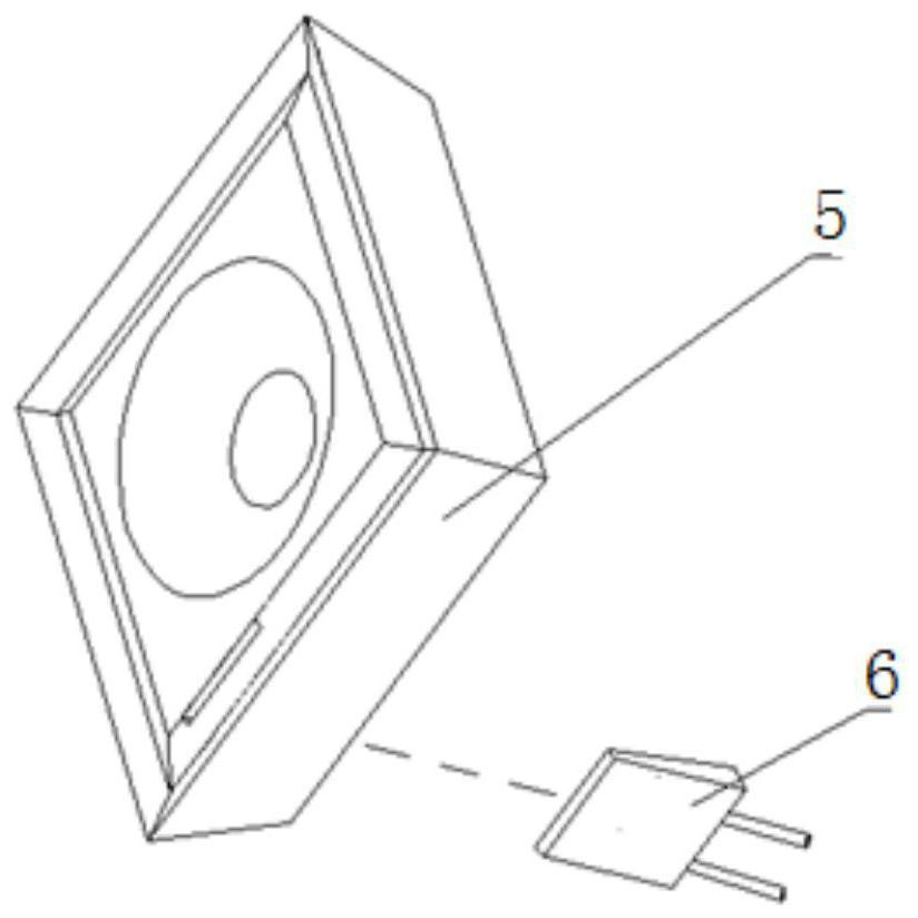
The invention provides a transient milling temperature testing device capable of following cutter-cutting contact abrasion. The transient milling temperature testing device comprises a milling cutter blade, a T-shaped milling cutter handle connected with the milling cutter blade in a matched mode, a temperature collecting and transmitting terminal embedded in the T-shaped milling cutter handle, and a thin film thermocouple temperature sensor capable of following abrasion and embedded in the front cutter face of the milling cutter blade. The thin film thermocouple temperature sensor capable of following abrasion is embedded in the front cutter face of the milling cutter blade, so that a hot contact of the sensor can follow abrasion and the sensor can be detached and replaced, and the problem that the temperature of a contact area between the front cutter face of a cutter and cuttings cannot be measured by a traditional measuring method is solved; and the temperature collecting and transmitting terminal is embedded in the cutter handle, so that a temperature signal can be wirelessly transmitted to a personal computer (PC) end in real time in the milling process to display the real-time temperature in a changing curve form, and a new method and a new technical approach are provided for transient temperature measurement in high-speed milling and precision machining.

Description

technical field [0001] The invention relates to the field of transient milling temperature detection technology and sensor technology, in particular to a milling temperature testing device based on a thin-film thermocouple temperature sensor. Background technique [0002] With the improvement of the automation and intelligence level of the processing system, especially in high-speed, precision and ultra-precision machining, the milling temperature and distribution are one of the key factors affecting tool life and processing quality. Among them, the accurate measurement of temperature and distribution in milling area has always been a hot spot and difficult problem in the research of milling mechanism. Milling temperature is one of the most important parameters in the high-speed milling process. During the cutting process, due to the combined effects of cutting force, cutting heat, cutting-in and cutting-out impact, etc., the contact surface between the tool and the workpiec...

Claims


Application Information

Patent Timeline
IPC IPC(8): B23C3/00B23C9/00B23Q17/09B23Q11/10
CPCB23C3/00B23C9/00B23Q11/10B23Q17/0985
Inventor 崔云先曹凯迪殷俊伟贾颖
Owner DALIAN JIAOTONG UNIVERSITY
Learn More