Chemical device emptying tail gas treatment waste heat recovery device

A waste heat recovery device and exhaust gas treatment technology, applied in the field of waste heat recovery, can solve the problems of inconvenient discharge of water and liquid filtration, inconvenient pressurized gas outlet speed, lack of water and liquid heat exchange treatment, etc., to increase the speed of exhaust , Increase cleanliness and facilitate disassembly

Inactive Publication Date: 2021-08-06
山东三岳化工有限公司
View PDF0 Cites 0 Cited by
  • Summary
  • Abstract
  • Description
  • Claims
  • Application Information

AI Technical Summary

Problems solved by technology

[0005] In order to solve the above technical problems, the present invention provides a waste heat recovery device for venting exhaust gas treatment of chemical plants to solve the problem that existing chemical plant venting tail gas treatment waste heat recovery devices do not have the ability to increase the introduction speed of waste gas, and it is inconvenient to process the discharged water. Filtration, there is no problem of heat exchange treatment for more water and inconvenient pressurization and gas outlet speed

Method used


Image

  • Chemical device emptying tail gas treatment waste heat recovery device
  • Chemical device emptying tail gas treatment waste heat recovery device
  • Chemical device emptying tail gas treatment waste heat recovery device

Examples


Embodiment

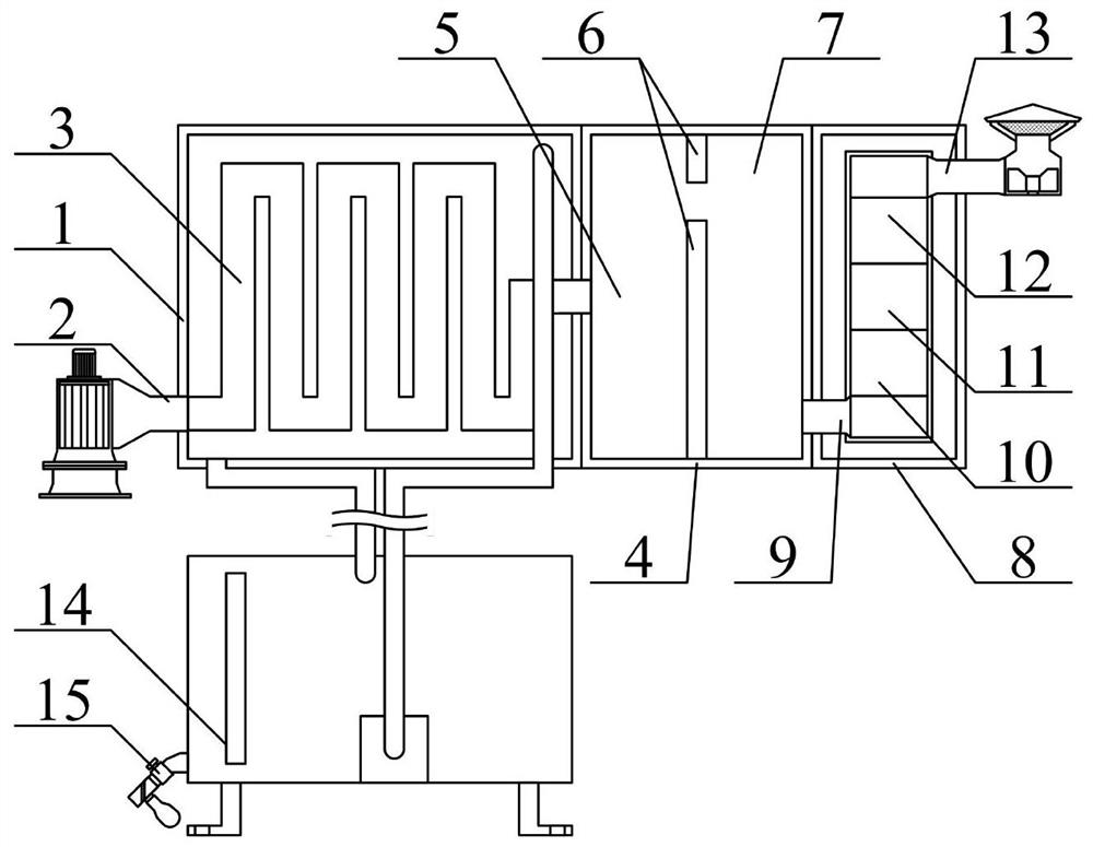
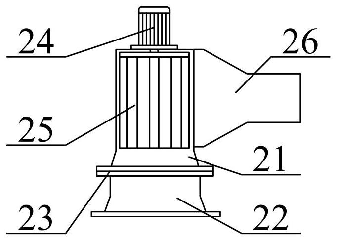
[0038] as attached figure 1 And attached figure 2 shown

[0039]The present invention provides a waste heat recovery device for exhaust gas treatment of a chemical plant, which includes a heat exchange box 1, a waste gas introduction frame structure 2, a serpentine pipe 3, a fixed outer frame 4, a particle trap 5, a longitudinal partition 6, and a reaction chamber 7 , a protective outer frame 8, a bottom conduit 9, a first catalytic layer 10, a second catalytic layer 11, a third catalytic layer 12, an auxiliary gas deriving frame structure 13, a water-liquid circulation heat exchange device 14 and a water-liquid discharge filter frame structure 15 , the exhaust gas introduction frame structure 2 is installed on the lower left side of the heat exchange box 1; the serpentine pipe 3 bolts are installed on the inner side of the heat exchange box 1; the fixed outer frame 4 bolts are installed on the heat exchange box The right side of 1; the left and right sides of the interior ...


PUM


Abstract

The invention provides a chemical device emptying tail gas treatment waste heat recovery device which comprises a heat exchange box, a waste gas guide-in frame structure, a snakelike pipeline, a fixed outer frame, a particle trap, a longitudinal partition plate, a reaction cavity, a protective outer frame, a bottom guide pipe, a first catalyst layer, a second catalyst layer, a third catalyst layer, an auxiliary gas guide-out frame structure, a water circulation heat exchanging device and a water discharging filtering frame structure, and the waste gas guiding-in frame structure is installed on the lower portion of the left side of the heat exchange box. The snakelike pipeline is installed on the inner side of the heat exchange box through bolts. The fixed outer frame is installed on the right side of the heat exchange box through bolts. The centrifugal fan blades are arranged at the upper part of the inner side of a conveying fixing frame, so that the speed of conveying waste gas into an output pipe can be increased during use. A longitudinal filter screen is mounted on the left side of the interior of an external pipe through a screw, so that water guided out of the external pipe can be conveniently filtered during use, and the cleanliness of the water guided out can be improved.

Description

technical field [0001] The invention belongs to the technical field of waste heat recovery, and in particular relates to a waste heat recovery device for exhaust gas treatment of a chemical plant. Background technique [0002] Waste heat refers to the sensible heat and latent heat that have not been rationally utilized in the original design in the industrial energy-consuming devices that have been put into operation due to the limitations of history, technology, and ideas. [0003] However, the existing waste heat recovery device for exhaust gas treatment of chemical plants has the disadvantages of not being able to increase the speed of exhaust gas introduction, not being able to filter the discharged water liquid, not being able to perform heat exchange treatment on more water liquid, and being inconvenient to pressurize the gas outlet speed. question. [0004] Therefore, it is very necessary to invent a kind of waste heat recovery device for exhaust gas treatment of che...

Claims


Application Information

Patent Timeline
Patent Type & Authority Applications(China)
IPC IPC(8): F27D17/00B01D53/86B01D45/06B01D35/027B08B15/00
CPCB01D35/027B01D45/06B01D53/869B01D2255/9025B08B15/00F27D17/004F27D17/008Y02P10/25
Inventor 路庆超史红辉王晓磊
Owner 山东三岳化工有限公司
Why Eureka
Try Eureka