
Anti-corrosion etching method for single-chip wet cleaning machine

A wet cleaning and machine technology, applied in cleaning methods and utensils, cleaning methods using liquids, chemical instruments and methods, etc., can solve problems such as increasing the risk of fragmentation, reducing etching uniformity, and low fault tolerance. Achieve the effect of reducing the risk of fragmentation, ensuring the uniformity of etching, and improving the fault tolerance rate

Pending Publication Date: 2021-08-06
HUA HONG SEMICON WUXI LTD
View PDF1 Cites 0 Cited by
  • Summary
  • Abstract
  • Description
  • Claims
  • Application Information

AI Technical Summary

Problems solved by technology

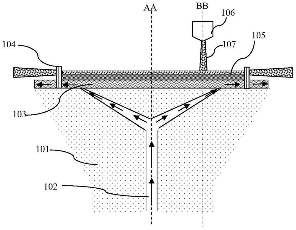
[0027] The first is that it is easy to produce fragments: this method has an increased risk of fragmentation in the wafer process where the thickness of the wafer 105 is less than 100 microns, which is not conducive to the further development of ultra-thin wafers with a thickness of less than 80 microns
[0028] The second is that it will reduce the etching uniformity (U%): after the thickness of the wafer 105 is further thinned (such as less than 80 microns), the wafer floats on the nitrogen pad 103 like a layer of paper, and the excessive nitrogen flow rate Will cause the wafer to fluctuate and etchU% will decrease;
[0029] The third is that the fault tolerance rate is low: this method will increase the dependence on the stability of the N2 at the factory service end. When the fluctuation of the N2 flow at the factory service end decreases, it will cause the wafer to continue to erode
[0032] Adverse effects: U% will be reduced: this method will lead to higher etching rate of the chemical solution, etch U% is difficult to control, and etchU% is reduced, which is not conducive to the control of wafer thickness of IGBT and other products, and then affects CP parameters such as VDSON and BV

Method used


Image

  • Anti-corrosion etching method for single-chip wet cleaning machine
  • Anti-corrosion etching method for single-chip wet cleaning machine
  • Anti-corrosion etching method for single-chip wet cleaning machine

Examples


Embodiment Construction

[0068] like Figure 5 Shown is the flow chart of the etching method for anti-corrosion of the monolithic wet cleaning machine platform of the embodiment of the present invention; Figure 6 As shown, it is a schematic cross-sectional structure diagram of the clamping device 101 in the etching method for anti-corrosion of the single-chip wet cleaning machine according to the embodiment of the present invention; Figure 7 As shown, it is a schematic diagram of the injection position of the liquid supply nozzle 106 in the etching method for anti-corrosion of the single-chip wet cleaning machine of the embodiment of the present invention; the anti-corrosion of the single-chip wet cleaning machine of the embodiment of the present invention The etching method comprises the following steps:

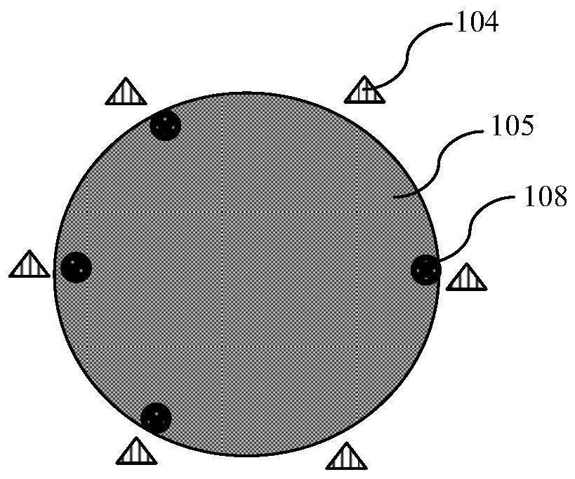
[0069] Step 1. Fix the wafer 105 on the clamping device 101 of the single-chip wet cleaning machine, the edge of the wafer 105 is in contact with the thimble 104 on the clamping device 101, and ...


PUM

PropertyMeasurementUnit
Thicknessaaaaaaaaaa

Abstract

The invention discloses an anti-corrosion etching method for a single-chip wet cleaning machine. The method comprises the steps that: step 1, a wafer is fixedly clamped on a clamping device, wherein the edge of the wafer is in contact with an ejector pin; step 2, the clamping device rotates and drives the wafer to rotate; and step 3, a liquid supply nozzle sprays a cleaning liquid to the first surface of the wafer for etching. During etching, the spraying position of the liquid supply nozzle is adjusted to achieve anti-corrosion, and the adjustment is implemented by the steps that: the spraying position of the liquid supply nozzle moves back and forth in a spraying interval; the circle center of the spraying interval coincides with the circle center of the wafer; and an acceleration interval of the cleaning liquid is formed between the edge of the spraying interval and the edge of the wafer, and the width of the acceleration interval ensures that all the cleaning liquid has the speed of being completely separated from the ejector pin when reaching the edge of the wafer through rotation acceleration. According to the a liquid supply nozzle method, reverse etching can occur in single-chip wet etching, the etching uniformity can be ensured, the chip breaking risk is reduced, and the error-tolerant rate is improved.

Description

technical field [0001] The invention relates to a method for manufacturing a semiconductor integrated circuit, in particular to an etching (etch) method for anti-reverse corrosion of a single-chip wet cleaning machine platform. Background technique [0002] Wafer (wafer) cleaning such as wafer backside cleaning is an important process in the wafer manufacturing process and is widely used in various product processes such as flash memory (Flash) and power (Power) devices. [0003] The wet cleaning process can be realized by using a batch (lot) of multi-chip cleaning, and can also be realized by single-chip cleaning. This application relates to an etching method for a single-chip wet cleaning machine. [0004] like figure 1 As shown, it is a schematic diagram of the cross-sectional structure of the clamping device in the etching method of the existing single-chip wet cleaning machine; figure 2 Shown is a schematic diagram of the injection position of the liquid supply nozz...

Claims


Application Information

Patent Timeline
IPC IPC(8): H01L21/02H01L21/67B08B3/02B08B3/08
CPCH01L21/02057H01L21/67051H01L21/6708B08B3/022B08B3/08
Inventor 陈裕谭秀文
Owner HUA HONG SEMICON WUXI LTD
Learn More