
Coating and application system and method for seed fertilizer and pesticide

A coating and hanger technology is applied in the fields of botanical equipment and methods, seed coating/seed dressing, layering/coating fertilizer, etc. Slow release of fertilizer and pesticide coating and automatic intelligent and precise control to ensure stability and effectiveness, quantitative and precise application effect

Active Publication Date: 2021-08-10
XIANGXI AUTONOMOUS PREFECTURE COMPANY HUNAN TOBACCO
View PDF14 Cites 1 Cited by
  • Summary
  • Abstract
  • Description
  • Claims
  • Application Information

AI Technical Summary

Problems solved by technology

The existing seeders have problems such as inconsistent seeding rate, broken seeds, and sowing on the ridge or edge of the hole in the seedling tray, and the seeder can only sow coated seeds without coating function; in terms of fertilization, most of them are artificially fertilized. Spreading or spraying with a sprayer leads to more labor, low efficiency, and high cost for tobacco leaf seedling cultivation, which directly affects the lean production and standardized production level of tobacco leaves

Method used


Image

  • Coating and application system and method for seed fertilizer and pesticide
  • Coating and application system and method for seed fertilizer and pesticide
  • Coating and application system and method for seed fertilizer and pesticide

Examples


Embodiment 1

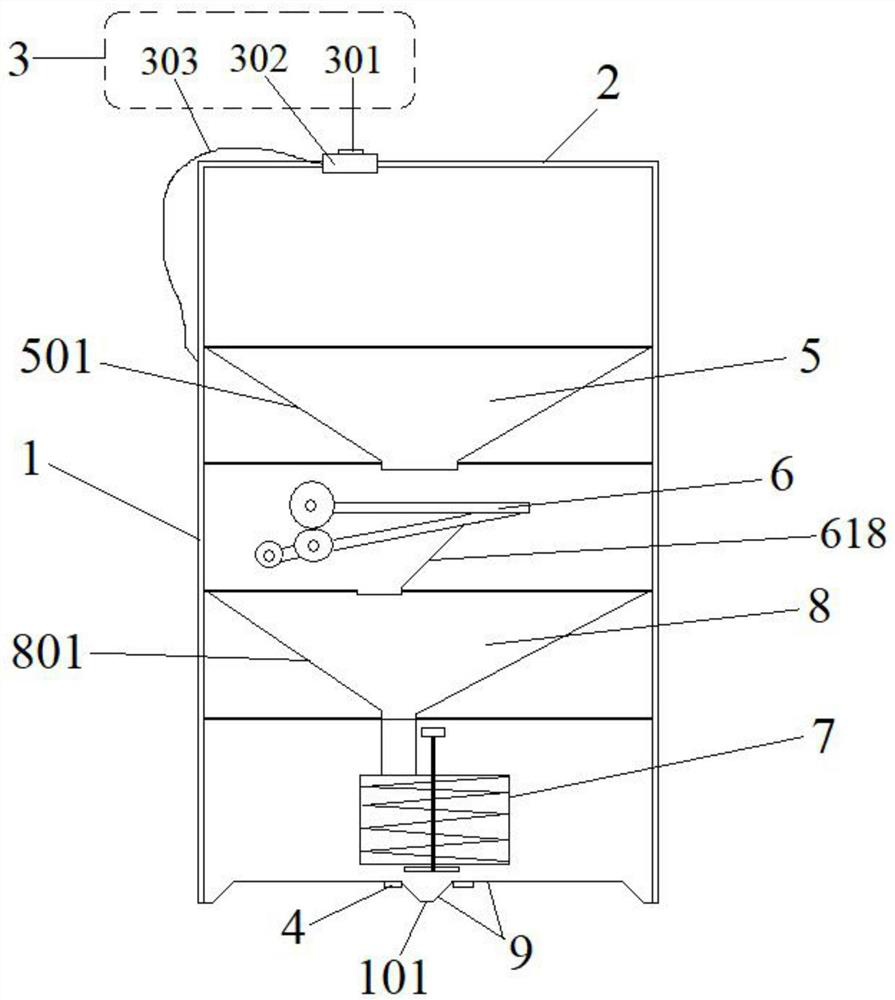
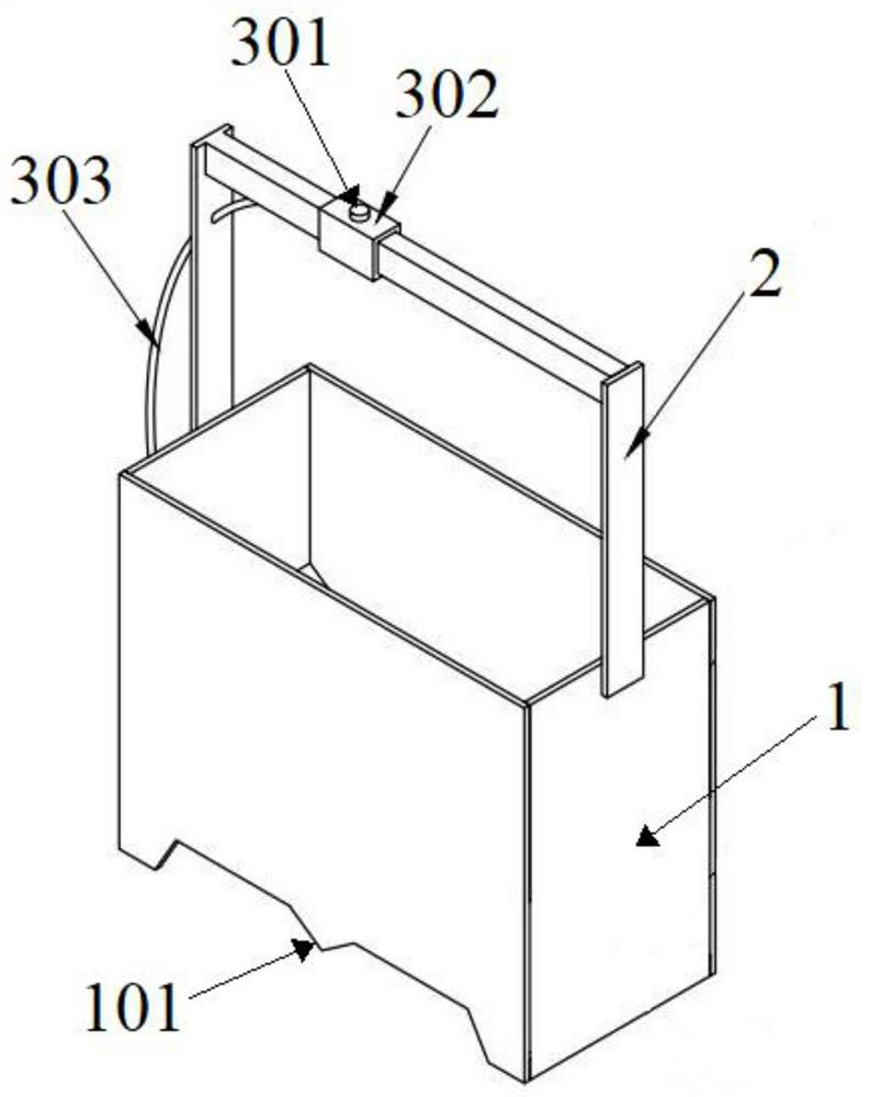
[0098] Such as Figure 1-2 As shown, a kind of fertilizer coating and application system, the system includes a box body 1 and a handle 2 arranged at the upper end of the box body 1 . The inner cavity of the box body 1 is provided with a feed box 5 , a roll-on coating device 6 and a discharge box 8 sequentially from top to bottom. The discharge port of the feed box 5 communicates with the feed port of the roll-on coating device 6 . The discharge port of the roll coating device 6 communicates with the feed port of the discharge box 8 . A control feeder 7 is also provided at the discharge port of the discharge box 8 .

Embodiment 2

[0100]Embodiment 1 is repeated, except that the system further includes a power supply device 3 . The power supply device 3 includes a power button 301 , a power supply 302 and a connection line 303 . The power button 301 is arranged on the handle 2 . The power supply 302 is arranged on the box body 1 or the handle 2 . The power supply 302 is independently connected to the feed box 5 , the roll-on coating device 6 , and the control discharge device 7 through the connection line 303 . That is, the power supply 302 independently controls the start and stop of the feed box 5 , the roll-up coating device 6 , the discharge device 7 and the opening and closing of their respective inlet and outlet ports through the connection line 303 .

Embodiment 3

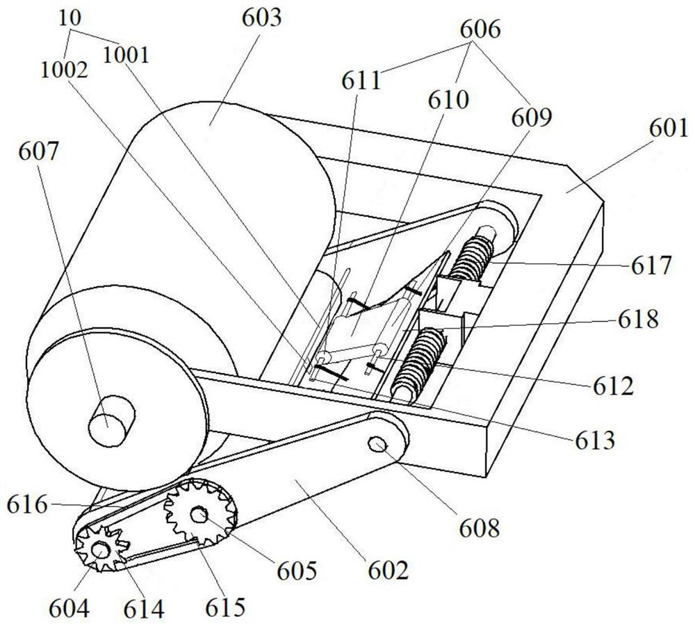
[0102] Repeat Example 2, such as image 3 As shown, only the rolling coating device 6 includes a clothes roll rack 601 , a clothes guide rack 602 , a clothes roll 603 , a first clothes guide shaft 604 , a second clothes guide shaft 605 and a material guide belt conveyor 606 . The top of the clothes guide rack 602 is movably connected with one end of the clothes roll rack 601 . The clothes roll 603 is arranged at the other end of the clothes roll rack 601 . The first clothes guiding shaft 604 is arranged at the bottom of the clothes guiding rack 602 . The second clothes guiding shaft 605 is arranged on the clothes guiding rack 602 and is located on the upper side of the first clothes guiding shaft 604 . The material guide belt conveyor 606 is arranged on the clothes guide rack 602 and is located on the upper side of the second clothes guide shaft 605 .


PUM

PropertyMeasurementUnit
lengthaaaaaaaaaa
widthaaaaaaaaaa
heightaaaaaaaaaa

Abstract

The invention discloses a coating and application system and method for seed fertilizer and pesticide. The system comprises a box body and a handle arranged at the upper end of the box body. A feeding box, a rolling type coating device and a discharging box are sequentially arranged in an inner cavity of the box body from top to bottom. A discharge hole of the feeding box is communicated with a feeding hole of the rolling type coating device. A discharge hole of the rolling type coating device is communicated with a feeding hole of the discharge box. A control discharger is further arranged at the discharge hole of the discharge box. The system is simple in structure, low in cost, easy to carry, high in applicability, uniform in coating and stable in coating quality, coating and application of seed fertilizer and pesticide can be achieved at the same time, and heating treatment is not needed. In addition, personalized layered coating operation can be realized.

Description

technical field [0001] The invention relates to seed fertilizer coating and application equipment, in particular to a seed fertilizer coating and application system and a coating and application method thereof, belonging to the technical field of agricultural production equipment. Background technique [0002] Seeds, fertilizers and pesticides play an important role in improving crop yield and quality in greenhouse crop production. At present, in the production process of greenhouses, there are two methods of sowing, one is artificial sowing, that is, artificially sow the seeds into the holes of the seedling tray, which is labor-intensive and susceptible to virus infection; the other is mechanical sowing, that is, through mechanical sowing. The seeds are sown into the holes of the seedling tray, but the machine has problems such as the crushing of the seed particles in the seed metering device and the blockage of the discharge holes. Although the labor is less, the emergence...

Claims


Application Information

Patent Timeline
Patent Type & Authority Applications(China)
IPC IPC(8): A01C1/06C05G5/30A01C7/00A01C15/00A01G13/00
CPCA01C1/06C05G5/30A01C7/00A01C15/00A01G13/00A01C15/005Y02P60/21
Inventor 张明发田峰张胜腾凯陈前锋田明慧
Owner XIANGXI AUTONOMOUS PREFECTURE COMPANY HUNAN TOBACCO
Learn More