A shrinkage cavity and shrinkage porosity prediction method for hot chamber die casting

A prediction method, hot chamber die-casting technology, applied in special data processing applications, design optimization/simulation, manufacturing computing systems, etc., can solve problems such as difficult to come out with accurate algorithms, affecting the service life of castings and product quality, and inaccurate predictions, etc. Achieve the effects of improving prediction accuracy, high accuracy, and ensuring calculation accuracy

Active Publication Date: 2021-08-10
宁波九寰适创科技有限公司 +1
View PDF7 Cites 2 Cited by
  • Summary
  • Abstract
  • Description
  • Claims
  • Application Information

AI Technical Summary

Problems solved by technology

[0002] In hot chamber die casting, during the solidification process after filling the mold, the liquid metal shrinks when it is cooled, resulting in shrinkage cavities, which seriously affect the service life and product quality of castings.
Due to the limitation of technical level, when predicting shrinkage cavity and shrinkage porosity, it is often necessary to rely on workers' years of experience or some empirical formulas to make qualitative guesses, and the prediction is very inaccurate
However, if quantitative simulation is required, it is necessary to use mold flow software for numerical simulation. At the same time, efficient parallel computing algorithms and high-performance computing and other hardware facilities must be used in the calculation. Various limitations make it difficult to come out with accurate algorithms for shrinkage cavity shrinkage prediction

Method used


Image

  • A shrinkage cavity and shrinkage porosity prediction method for hot chamber die casting
  • A shrinkage cavity and shrinkage porosity prediction method for hot chamber die casting
  • A shrinkage cavity and shrinkage porosity prediction method for hot chamber die casting

Examples


Embodiment Construction

[0029] Embodiments of the present invention are described in detail below, examples of which are shown in the drawings, wherein the same or similar reference numerals designate the same or similar elements or elements having the same or similar functions throughout. The embodiments described below by referring to the figures are exemplary and are intended to explain the present invention and should not be construed as limiting the present invention.

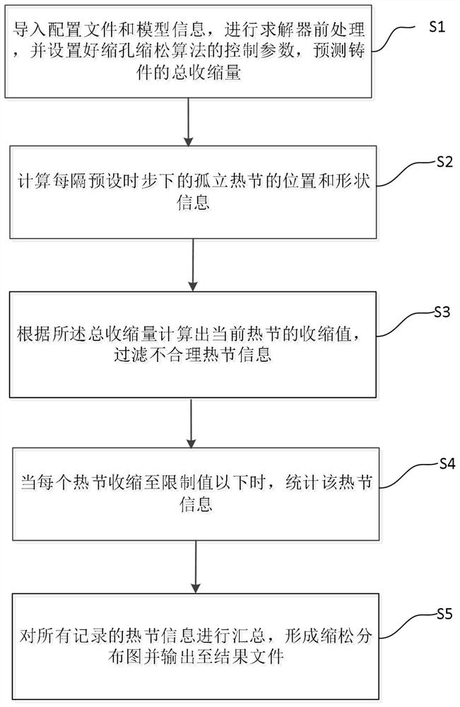
[0030] Such as figure 1 As shown, the shrinkage cavity shrinkage prediction method for hot chamber die casting according to the embodiment of the present invention includes:

[0031] Step S1, import the configuration file and model information, perform pre-processing of the solver, and set the control parameters of the shrinkage cavity shrinkage algorithm to predict the total shrinkage of the casting.

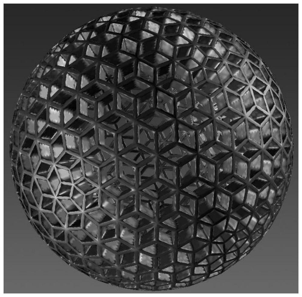
[0032] Specifically, such as image 3 As shown in the calculation example of the Lenger sphere, the temperature change process...


PUM


Abstract

The invention provides a shrinkage cavity and shrinkage porosity prediction method for hot chamber die casting, which comprises the following steps: S1, importing a configuration file and model information, performing solver pretreatment, setting control parameters of a shrinkage cavity and shrinkage porosity algorithm, and predicting the total shrinkage amount of a casting; s2, calculating the position and shape information of the isolated hot spot at every preset time step; s3, calculating the shrinkage value of the current hot spot according to the total shrinkage amount, and filtering unreasonable hot spot information; s4, when each hot spot is shrunk below a limit value, counting information of the hot spot; and S5, summarizing all the recorded hot spot information to form a shrinkage distribution diagram, and outputting the shrinkage distribution diagram to a result file.

Description

technical field [0001] The invention relates to the technical field of injection molding, in particular to a shrinkage cavity and porosity prediction method for hot chamber die casting. Background technique [0002] In hot chamber die-casting, during the solidification process after filling, the liquid metal shrinks when it is cooled, resulting in shrinkage cavities, which seriously affect the service life and product quality of castings. Due to the limitations of the technical level, when predicting shrinkage porosity, it is often necessary to rely on workers' years of experience or some empirical formulas to make qualitative guesses, and the predictions are very inaccurate. However, if quantitative simulation is required, it is necessary to use mold flow software for numerical simulation. At the same time, high-efficiency parallel computing algorithms and high-performance computing hardware facilities must be used in the calculation. Various limitations make it difficult t...

Claims


Application Information

Patent Timeline
Patent Type & Authority Applications(China)
IPC IPC(8): G06F30/23
CPCG06F30/23Y02P90/30
Inventor 张子珂李忠林向东张伟
Owner 宁波九寰适创科技有限公司
Why Eureka
Try Eureka