Cable laying construction method

A construction method and cable laying technology, applied in the directions of cable laying equipment, cable installation, optical fiber/cable installation, etc., can solve the problems of reduced cable current carrying capacity, increased energy consumption of cable sheath, increased cable temperature, etc. Number of wells, reduction of laying depth, effect of reducing negative effects

Active Publication Date: 2021-08-10
GUANGDONG WEIHENG POWER TRANSMISSION & DISTRIBUTION ENG +1
View PDF8 Cites 0 Cited by
  • Summary
  • Abstract
  • Description
  • Claims
  • Application Information

AI Technical Summary

Problems solved by technology

[0003]1. For laying cables, it is necessary to directly dig the road surface to bury pipes or make cable trenches, which will break the intestines of the city and have a great negative impact on society
[0004]2. The urban underground pipeline network is complex, and it is difficult to completely avoid existing important pipelines (gas, electricity, military optical cables, etc.) during excavation, and other underground pipelines will be caused by excavation. There is a high risk of damage; excavation of the road surface will affect traffic and often cause traffic congestion. The project is often stopped by the traffic management department, and the implementation of the project is very difficult
[0005]3. At present, the buried pipes of 110kV and above cables are all made of non-magnetic plastic pipes. The thermal conductivity of plastic is poor, which is equivalent to wearing a warm clothes on the cables. , the accumulation of heat leads to the reduction of the carrying capacity of the cable laid in the pipeline, which becomes the bottleneck of the cable transmission of electric energy
[0006]4. Cables of 110kV and above are mostly laid in parallel after passing through the pipe. Since each pipe only passes through one cable, the distance between the three cables is relatively small. The electromagnetic induction cannot be well offset. On the one hand, the induction energy consumption of the cable sheath increases, and the energy consumption and heating increase the temperature of the cable as a whole, further reducing the current carrying capacity of the cable core; on the other hand, the electromagnetic may affect the adjacent communication line interference
[0007]5. Plastic pipes have poor strength and are easily damaged by external forces. They cannot protect cables well, and in severe cases, they will endanger the stability and safety of power transmission

Method used


Image

  • Cable laying construction method
  • Cable laying construction method
  • Cable laying construction method

Examples


Embodiment 1

[0050] like Figures 1 to 3 Shown, cable laying construction method of the present invention comprises the following steps:

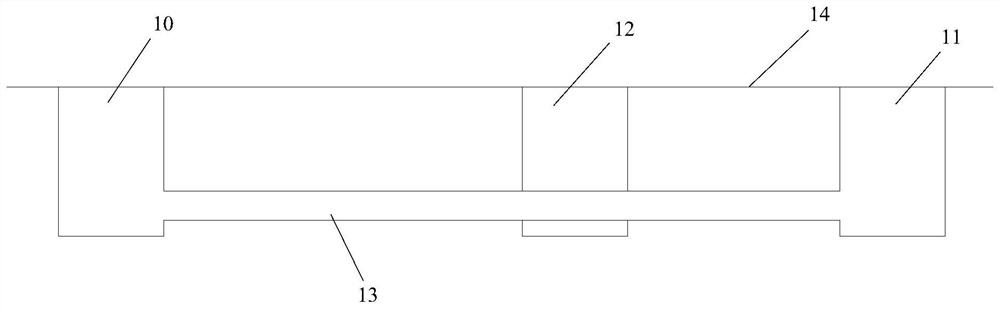
[0051]The first step is to set the pipeline 13 for laying cables;

[0052] In the second step, a cable jacking shaft 10 and a cable receiving shaft 11 are set up on the ground 14, and a pipeline jacking device is used in the underground to carry out the jacking operation of the pipeline from the cable jacking shaft 10 to the cable receiving shaft 11 to lay the pipeline; specifically Said, the laying depth of the pipeline 13 is 4-5 meters, the pipeline jacking device comprises a thrust device and a tool pipe, the pipeline 13 is offset against the tool pipe, and the thrust device is used to push the pipeline 13, and the tool pipe moves toward the soil layer under the thrust of the thrust device. Inner excavation, the excavated soil is discharged to realize the jacking and laying of the pipeline 13 to the soil layer; finally, the tool pipe is hoisted from...

Embodiment 2

[0069] The difference between this embodiment and Embodiment 1 is that the magnetic isolation structure refers to: each middle tube is a non-closed structure with an opening, the opening faces the gap, and the gap is provided with a non-magnetic material, wherein the non-magnetic material is stainless steel , copper and aluminum etc.

[0070] Other structures of this embodiment are consistent with Embodiment 1.

Embodiment 3

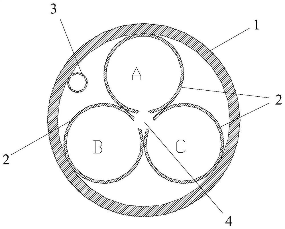
[0072] This embodiment differs from Embodiment 1 only in that: Figure 4 As shown, the pipe joints of this embodiment are pipe joints made of metal or reinforced concrete, and each pipe joint is prefabricated with three through holes 8 and a small through hole 9, and the three cables A, B and C of the same circuit respectively pass through the through holes 8 , and the communication optical cables pass through the small through holes 9 . Wherein, the three through-holes 8 are arranged to form a zigzag, so that the three cables passing through the three through-holes 8 are arranged in a zigzag.

[0073] In this embodiment, there are gaps 4 in the middle of the three through-holes 8 arranged in the shape of a character. The through-holes 8 are provided with a magnetic isolation structure for making the single-core cable in a non-closed magnetic circuit. The magnetic isolation structure refers to: each through-hole 8 It is a non-closed structure with an opening, the opening face...


PUM


Abstract

The invention provides a cable laying construction method. The method comprises the steps of 1, setting a pipeline for laying a cable; 2, arranging a cable jacking well and a cable receiving well, and carrying out pipeline jacking operation from the cable jacking well to the cable receiving well by adopting a pipeline jacking device underground so as to lay a pipeline; and 3, laying three cables A, B and C in the same loop into the same pipeline so as to realize the laying of the cables, wherein the pipeline is formed by inserting or welding a plurality of pipe sections. According to the cable laying construction method, the pipeline of the cable can be laid in a non-excavation ground mode, so that cable laying is achieved, and the excavation amount is greatly reduced. In addition, according to the method, the construction period can be greatly shortened, and the quality and the service life of the laid cable are guaranteed.

Description

technical field [0001] The invention relates to the technical field of cable construction, and more specifically relates to a cable laying construction method. Background technique [0002] With the rapid development of my country's electric power construction and the deepening of urban beautification requirements, the application occasions of cables are gradually increasing. Cables have many uses, mainly used to control connection equipment, transmit power and other functions, and are common and indispensable power transmission materials in production and life. Among them, 110kV and above single-core cables are generally laid in trenches and pipelines. The closer to the urban area, the greater the proportion of cable laying. The methods currently used for cable laying suffer from the following drawbacks: [0003] 1. To lay cables, it is necessary to directly dig the road surface to bury pipes or make cable trenches, which will break the intestines of the city and have a g...

Claims


Application Information

Patent Timeline
Patent Type & Authority Applications(China)
IPC IPC(8): H02G1/08H02G3/06H02G9/06H02G9/10G02B6/50
CPCH02G1/08H02G3/06H02G9/06H02G9/065H02G9/10G02B6/50
Inventor 张立林廖志鹏林金荧曾龙兴李文杰赵敏坚
Owner GUANGDONG WEIHENG POWER TRANSMISSION & DISTRIBUTION ENG
Why Eureka
Try Eureka