Low-phase noise frequency source circuit

A low phase noise, frequency source technology, applied in the direction of electrical components, power automatic control, etc., can solve the problems of poor DDS output harmonics and spurious suppression, affecting the radar's ability to distinguish targets, and difficult low phase noise signals, etc. , to achieve the effects of low spurs, faster frequency locking time, and high frequency resolution

Active Publication Date: 2021-08-13
CHENGDU WEIPIN COMM TECH CO LTD
View PDF11 Cites 0 Cited by
  • Summary
  • Abstract
  • Description
  • Claims
  • Application Information

AI Technical Summary

Problems solved by technology

[0004] In a radar system, phase noise will cause a decrease in the baseband signal-to-noise ratio, thereby affecting the radar's ability to distinguish targets
Prior art CN105656476A discloses a low-phase-noise radar frequency source generation circuit, which uses FPGA to control DDS. Although low-phase-noise frequency is realized, the output frequency of the integrated DDS chip is low, and DDS output harmonics and spurious suppression are poor , it is difficult to realize the output of higher frequency low phase noise signal; prior art CN112187259A discloses a kind of broadband agile frequency source, which adopts a ping-pong ring circuit structure, and the frequency output by multiple phase-locked loops is mixed with the local oscillator module, Although a broadband-agile frequency source is realized, the circuit structure is complex, debugging is difficult, the cost is high, and the frequency resolution is not high

Method used


Image

  • Low-phase noise frequency source circuit
  • Low-phase noise frequency source circuit
  • Low-phase noise frequency source circuit

Examples


Embodiment 1

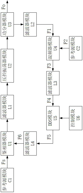
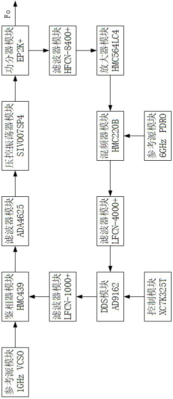
[0038] Such as figure 2 As shown, it is a schematic diagram of a low phase noise frequency source circuit in Embodiment 1 of the present application.

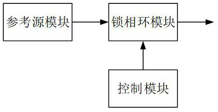
[0039]The working principle is as follows: through the basic phase-locked loop circuit, it can be known that the input signal of the reference source module C1 is input to the reference input terminal of the phase detector module U1, and then the reference input terminal and the feedback input terminal of the phase detector module U1 pass through the internal phase detection. When the phase of the two input signals is not constant, the phase detector module U1 will generate a control voltage to the filter module L1, that is, the loop filter, and the loop filter will filter out the high-frequency signal in the control voltage, and then generate a control voltage The pure control voltage is given to the voltage-controlled oscillator module U2, and the control voltage is linearly related to the output frequency of the voltage-con...

Embodiment 2

[0048] Such as Figure 4 As shown, it is a circuit schematic diagram of a low-phase-noise fast frequency-variable source according to Embodiment 2 of the present application.

[0049] On the basis of the first embodiment, the second embodiment further includes: a DAC module U7 and an adder module U8.

[0050] Specifically, the DAC module U7 is connected to the control module U6 and the adder module U8, and the adder module U8 is connected between the filter module L1 and the voltage-controlled oscillator module U2.

[0051] Therefore, when the phase detector module U1 converts the frequency difference into a control voltage V1 through the internal charge pump, the control module U6 converts the corresponding data into a voltage V3 through the DAC module U6 through calculation, so that the DAC module through the adder module U8 The preset voltage V3 supplied by U7 to the oscillator module U2 is added to the control voltage V2 generated by the phase detector module U1 after pas...

Embodiment 3

[0054] Such as Figure 6 As shown, it is a circuit schematic diagram of a low-phase-noise fast variable-bandwidth frequency source in Embodiment 3 of the present application.

[0055] On the basis of the second embodiment, the third embodiment further includes: a switch module U9, a reference source module C3, a reference source module C4, and a reference source module C5.

[0056] Specifically, the switch module U9 is connected to the control module U6 and the mixer module U4, and the switch module U9 is simultaneously connected to the reference source module C2, the reference source module C3, the reference source module C4, and the reference source module C5.

[0057] It works as follows:

[0058] The input signal of the reference source module C1 is input to the reference input terminal of the phase detector module U1, and then the reference input terminal and the feedback input terminal of the phase detector module U1 pass internal phase detection. When the phases of the...


PUM


Abstract

A low-phase noise frequency source circuit comprises a phase discriminator module, two reference source modules, four filter modules, a voltage-controlled oscillator module, a power divider module, a frequency mixer module, a DDS module and the like; the phase discriminator module performs frequency discrimination and phase discrimination on a reference input signal and a feedback input signal, and converts a frequency difference into a control voltage signal; the filter module converts the control voltage signal into a tuning voltage signal; the voltage-controlled oscillator module converts the tuning voltage signal into a frequency signal; the power divider module divides the frequency signal into a direct output signal and a feedback frequency signal; the frequency mixer module mixes the feedback frequency signal and a second reference input signal; the DDS module processes the frequency mixing signal according to a frequency control word FTW and outputs a tuning frequency signal; the filter module processes the tuning frequency signal into a feedback input signal. Low output frequency phase noise and high resolution are realized, rapid frequency hopping is realized, the output bandwidth of the frequency source can be expanded, and a wide frequency band is realized.

Description

technical field [0001] The invention relates to a radio frequency microwave frequency source, in particular to a low phase noise frequency source circuit. Background technique [0002] A frequency source is a component widely used in circuits. Its function is to provide accurate clock signals to various devices, and it plays an important role in modern electronic communication systems. At present, the frequency source is developing towards the performance index of broadband, fast change, and low phase noise, especially in the fields of electronic countermeasures, radar systems, instrumentation, and radio frequency microwaves, high-performance frequency sources are required. The most important technical method of the frequency source is the frequency synthesis technology, which is to synthesize a new frequency from the reference frequency through a series of frequency conversion methods such as frequency mixing, frequency multiplication or frequency division. [0003] At pre...

Claims


Application Information

Patent Timeline
IPC IPC(8): H03L7/18
CPCH03L7/18
Inventor 刘国超刘畅王明杜姗姗
Owner CHENGDU WEIPIN COMM TECH CO LTD
Why Eureka
Try Eureka