Specimen pretreatment device applied to pathology department
A pretreatment device and a technology for specimens, applied in the field of pathology, can solve the problems of unsatisfactory air-drying effect, environmental pollution, air-drying of sampled tissue, etc.
- Summary
- Abstract
- Description
- Claims
- Application Information
AI Technical Summary
Problems solved by technology
Method used
Image
Examples
Embodiment 1
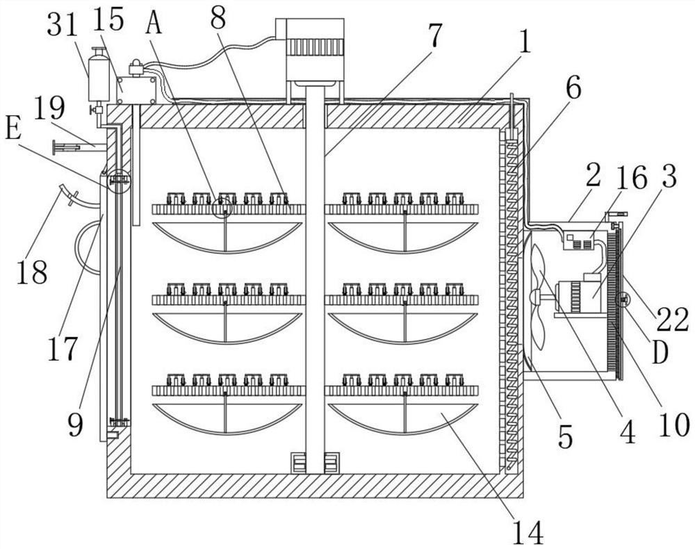
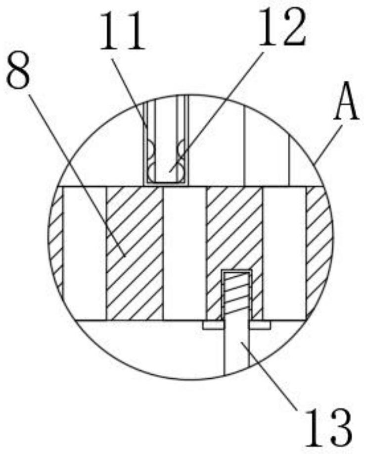
[0031] see Figure 1-2 and Figure 9-10, a pathological specimen preprocessing device, comprising a device main body 1, a protective case 2 is fixedly connected to the right side of the device main body 1, a motor 3 is installed inside the protective case 2, and a fan blade 4 is fixedly connected to the output end of the left side of the motor 3, The right side of the device main body 1 is fixedly connected with an air intake cover 5, and the inside of the right side wall of the device main body 1 is provided with an empty chamber, and the inside of the empty chamber is provided with a heating wire 6, and the left side of the empty chamber is uniformly provided with an air inlet hole, and the device The middle part of the top surface of the main body 1 is movably connected with a main rod 7, and the left and right sides of the surface of the main rod 7 are uniformly fixedly connected with a receiving plate 8, and the top surface of the receiving plate 8 is uniformly provided w...
Embodiment 2
[0037] see Figure 4-6 , the left side of the device main body 1 is hinged with a first cover plate 17, the left side of the first cover plate 17 is fixedly connected with a push rod 18, the surface of the push rod 18 is fixedly connected with a limit block 20, and the left side of the device main body 1 is fixedly connected with There is a top plate 19, the bottom surface of the top plate 19 is provided with a fixed groove compatible with the push rod 18, the left side of the fixed groove inner wall is movably connected with a plunger 21, and the surface of the push rod 18 is provided with a plug fit with the plunger 21. groove.
[0038] The right side of the protective shell 2 is movably connected with a second cover plate 22, and the top of the protective shell 2 is fixedly connected with a connecting block 23. The connecting block 23 is designed in an L shape, and the front of the connecting block 23 is provided with a transverse groove 24. The second cover plate The fron...
Embodiment 3
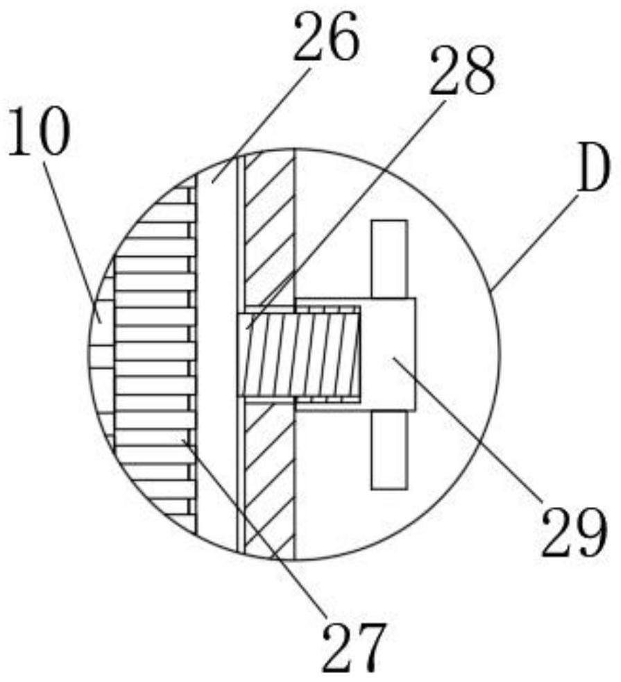
[0041] see image 3 and Figure 7-8 , the left side of the second cover plate 22 is provided with a groove, the inner wall of the groove is movably connected with a brush block 26, the left side of the brush block 26 is evenly and fixedly connected with bristles 27, and the right side of the brush block 26 is fixedly connected with a threaded rod 28 , the right end of the threaded rod 28 passes through the side of the second cover plate 22 and is threadedly connected with a threaded barrel 29 .
[0042] The left and right sides of the top and bottom of the perforated inner wall are fixedly connected with vertical blocks, and a screw 30 is movably connected between the vertical blocks on both sides, and one end of the screw 30 passes through the side of the catch 9, which is made of dark non-woven fabric It is composed of three layers of meltblown nonwoven fabric and spunbonded nonwoven fabric.
[0043] The left side of the device main body 1 is provided with a cavity, the in...
PUM
 Abstract
Description
Claims
Application Information
 - R&D
- Intellectual Property
- Life Sciences
- Materials
- Tech Scout
- Unparalleled Data Quality
- Higher Quality Content
- 60% Fewer Hallucinations
Browse by: Latest US Patents, China's latest patents, Technical Efficacy Thesaurus, Application Domain, Technology Topic, Popular Technical Reports.
© 2025 PatSnap. All rights reserved.Legal|Privacy policy|Modern Slavery Act Transparency Statement|Sitemap|About US| Contact US: help@patsnap.com


