
Engine cylinder surface defect detection method and system based on machine vision

A technology for engine block and defect detection, which is applied in the direction of optical testing for defects/defects, instruments, measuring devices, etc. It can solve problems such as the state and size of defects, product inflow, and judgment differences in the qualification of limit parts, etc., to reduce Labor intensity, increase detection speed, and reduce maintenance cost

Pending Publication Date: 2021-08-17
菲特(天津)检测技术有限公司
View PDF11 Cites 8 Cited by
  • Summary
  • Abstract
  • Description
  • Claims
  • Application Information

AI Technical Summary

Problems solved by technology

[0005] (1) The traditional way is to use artificial methods: workers use human eyes to identify and detect the measured objects. During long-term single repetitive work, workers are prone to fatigue, resulting in unqualified products flowing into the application market
[0006] (2) Different workers operate with different degrees of latitude and strictness, and there will be corresponding differences in the judgment of the qualification of limit parts
[0007] (3) There are many inspection surfaces of the engine cylinder block, and there is a height difference between the processing surfaces. The camera cannot be guaranteed to be at the same height. The causes of defects are complex, and there are many problems in machine vision inspection.
[0008] The difficulty in solving the above technical problems lies in: there are many types of defects on the surface of the cylinder body, there is a height difference in the processing surface, and the camera has a depth of field problem, so the camera cannot be guaranteed to be at the same height, and the defect position exists anywhere on the surface, and the state and size of the defect are different.

Method used


Image

  • Engine cylinder surface defect detection method and system based on machine vision
  • Engine cylinder surface defect detection method and system based on machine vision
  • Engine cylinder surface defect detection method and system based on machine vision

Examples


Embodiment Construction

[0063] In order to make the above objects, features and advantages of the present invention more comprehensible, specific implementations of the present invention will be described in detail below in conjunction with the accompanying drawings. In the following description, numerous specific details are set forth in order to provide a thorough understanding of the present invention. However, the present invention can be implemented in many other ways different from those described here, and those skilled in the art can make similar improvements without departing from the connotation of the present invention, so the present invention is not limited by the specific implementations disclosed below.

[0064] It should be noted that when an element is referred to as being “fixed” to another element, it can be directly on the other element or there can also be an intervening element. When an element is referred to as being "connected to" another element, it can be directly connected ...


PUM


Abstract

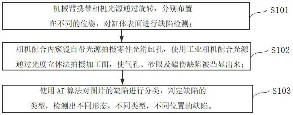
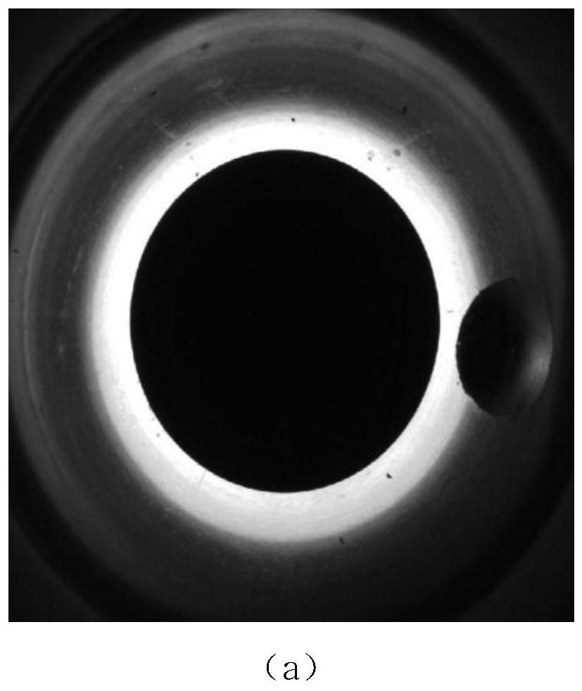
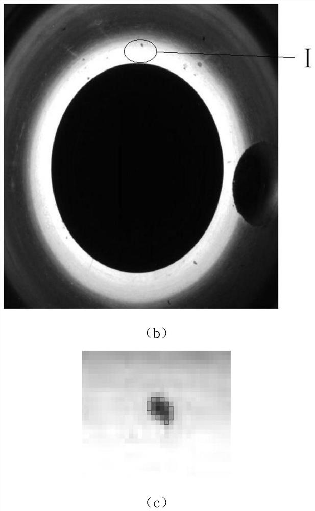
The invention discloses an engine cylinder surface defect detection method and system based on machine vision, and relates to the technical field of image processing and AI algorithms. A mechanical arm carries a camera light source to be arranged at different poses through rotation, and defect detection is carried out on the surface of the cylinder body; a camera is matched with a light source of an endoscope lens to shoot a smooth cylinder hole of a part, and an industrial camera is matched with the light source to shoot a machining surface through a photometric stereo method, so that air holes, sand holes and gouges are highlighted; and the defects of the picture are classified by using an AI algorithm, the types of the defects are judged, and the defects of different forms, different types and different positions are detected. According to the invention, manpower can be saved, labor intensity is reduced, maintenance cost is reduced, and shooting precision and detection speed are improved; for defects of different forms, different types and different positions, the detection effect can reach 99.95%, and it is indicated that the method is suitable for engine cylinder surface defect detection.

Description

technical field [0001] The disclosure of the present invention relates to the technical field of image processing and AI algorithm, and in particular to a method and system for detecting surface defects of engine cylinder block based on machine vision. Background technique [0002] As one of the important parts in the field of modern industrial manufacturing, the cylinder block is widely used in the fields of petroleum, national defense, aerospace and automobile industry. The cylinder block is the basic part of the car engine, which constitutes the main frame of the engine. The engine is one of the most core components of the car and is the source of power for the car to run. Through the cylinder block of the engine, various mechanisms, such as the crank connecting rod mechanism (including pistons, connecting rods, crankshafts, etc.) and the valve mechanism (including intake and exhaust valves, valve springs, etc.) Mechanisms are connected as a whole to form a complete car...

Claims


Application Information

Patent Timeline
Patent Type & Authority Applications(China)
IPC IPC(8): G01N21/01G01N21/95
CPCG01N21/01G01N21/9515
Inventor 袁帅鹏杜金月王立起陈涛王敏雪周学博田楷
Owner 菲特(天津)检测技术有限公司
Learn More