
Device and method for testing control logic of start-stop system of high-temperature gas cooled reactor

A high-temperature gas-cooled reactor shutdown system technology, applied in the field of high-temperature gas-cooled reactor startup and shutdown systems, can solve problems such as poor applicability, economic losses, and errors in reading test results, so as to achieve stable operation and improve reliability sexual effect

Pending Publication Date: 2021-08-17
XIAN THERMAL POWER RES INST CO LTD
View PDF4 Cites 0 Cited by
  • Summary
  • Abstract
  • Description
  • Claims
  • Application Information

AI Technical Summary

Problems solved by technology

There are at least the following problems in this test method: when the operating conditions of the start-stop reactor system are complex and there are many measurements, the above manual test method has the disadvantages of reading errors and many errors in the test results, and the test efficiency is low; at the same time , the DCS logic needs to be modified during the test to simulate various operating states of the system. Since the start-stop reactor system involves the whole process of operating conditions during the unit start, stop and power operation stages, the DCS logic involved is relatively wide, and the test process directly Modifying the DCS logic will bring hidden dangers to the subsequent stable operation of the unit, and the applicability of the above test methods is poor
When it is heavy, it will cause the filter material to harden, which not only affects the normal operation of the filter, but also brings certain economic losses.

Method used


Image

  • Device and method for testing control logic of start-stop system of high-temperature gas cooled reactor

Examples


Embodiment 1

[0043] Taking the 200MW high-temperature gas-cooled reactor unit as an example, two sets of nuclear steam supply systems are used to connect one steam turbine to form a nuclear power unit. The thermal power of each nuclear steam supply system is 250MW, the total thermal power is 500MW, and the electric power is 211MW. The primary loop of the reactor uses helium as the coolant, and the operating pressure is 7MPa. The pressure of the water supply system of the secondary loop of the reactor is the rated parameter during the whole process of operation, that is, the outlet medium pressure of the steam generator is 13.90MPa, and the design pressure of the steam-water separator is 6.4MPa. The rated operating pressure is 5MPa, and the design temperature is 370°C.

[0044] Concrete work process of the present invention is:

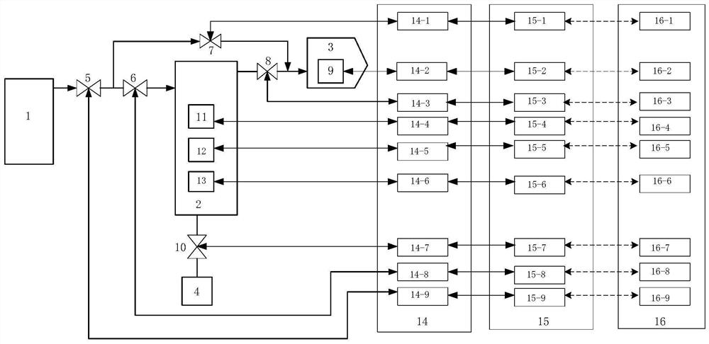
[0045] (1) Verification of the commissioning process of steam-water separator 2:

[0046] The simulation modeling server 16 simulates the reactor to start (the r...


PUM


Abstract

A device for testing control logic of a start-stop system of a high-temperature gas cooled reactor comprises a steam generator, the steam generator is connected with a steam-water separator inlet regulating valve, the steam-water separator inlet regulating valve is divided into two paths, one path is connected with a steam-water separator inlet isolating valve, the steam-water separator inlet isolating valve is connected with a steam-water separator, and the steam-water separator first outlet is connected with a steam-water separator outlet isolating valve; the other path is connected with a steam-water separator bypass regulating valve, and the steam-water separator outlet isolating valve and an outlet of the steam-water separator bypass regulating valve are converged and then are connected into a main steam collecting pipe; and a second outlet of the steam-water separator is connected with a steam-water separator drain regulating valve, and an outlet of the steam-water separator drain regulating valve is connected with a drain tank. And the steam-water separator internal monitoring device and each valve of the steam-water separator are respectively connected with a simulation modeling server through a start-stop reactor system DCS cabinet via a PXI data acquisition cabinet. According to the invention, the actual functions of the start-stop reactor system can be verified in advance, and the test efficiency is improved.

Description

technical field [0001] The invention relates to the technical field of high-temperature gas-cooled reactor startup and shutdown systems, in particular to a test device and method for the control logic of the high-temperature gas-cooled reactor startup and shutdown system. Background technique [0002] The start-stop reactor system is an important part of the pebble bed modular high-temperature gas-cooled reactor nuclear power plant. During the start-up and stop of the unit, the system is mainly used to adjust the steam parameters at the outlet of the nuclear island steam generator to meet the start-up requirements of the steam turbine. The steam generator exports steam to the condenser to take away the heat generated by the reactor and ensure the cooling requirements of the steam generator and the reactor. [0003] The high temperature gas-cooled reactor start-stop reactor system includes a steam-water separation system and a working fluid state parameter control system comp...

Claims


Application Information

Patent Timeline
IPC IPC(8): G21C17/028G21D3/04
CPCG21C17/028G21D3/04Y02E30/00Y02E30/30
Inventor 刘俊峰李泽华蔡宝玲韩传高余俨
Owner XIAN THERMAL POWER RES INST CO LTD
Learn More