
Process and system for combining waste electricity hydrogen production with circulating fluidized bed boiler combustion

A circulating fluidized bed and boiler combustion technology, applied in the direction of combustion air/fuel supply, combustion methods, chemical industry, etc., can solve the problems of large thermal inertia, limit the deep peak-shaving performance of circulating fluidized bed boilers, etc., and achieve improved The effect of fluidizing wind speed, solving fluidization safety problems, and improving response speed

Pending Publication Date: 2021-08-20
TSINGHUA UNIV
View PDF7 Cites 0 Cited by
  • Summary
  • Abstract
  • Description
  • Claims
  • Application Information

AI Technical Summary

Problems solved by technology

Circulating fluidized bed boilers are different from conventional pulverized coal boilers. Since the materials in circulating fluidized bed boilers stay in the furnace for a long time, the combustion inertia in the circulating fluidized bed furnace and the thermal inertia of the bed materials are relatively large, resulting in the circulation flow The fluidized bed boiler generator set has the characteristics of large thermal inertia. It is difficult to change the boiler load quickly by changing the amount of fuel added. Therefore, both the load reduction rate and the load increase rate of the circulating fluidized bed boiler are affected by thermal inertia, which limits the efficiency of the circulating fluidized bed boiler. Deep Peak Shaving Performance of Boiler

Method used


Image

  • Process and system for combining waste electricity hydrogen production with circulating fluidized bed boiler combustion
  • Process and system for combining waste electricity hydrogen production with circulating fluidized bed boiler combustion
  • Process and system for combining waste electricity hydrogen production with circulating fluidized bed boiler combustion

Examples


Embodiment approach

[0034] A typical implementation of the present invention provides a process for producing hydrogen from waste electricity combined with combustion in a circulating fluidized bed boiler, including a hydrogen production process from electrolyzed water and a combustion and power generation process in a circulating fluidized bed boiler;

[0035] During deep peak shaving, a part of the flue gas from the combustion power generation process of the circulating fluidized bed boiler is extracted as the circulating flue gas, a part of the circulating flue gas is mixed with air or oxygen to obtain primary air, and the primary air enters the furnace from the lower part of the furnace as fluidized air. Mix another part of the circulating flue gas with oxygen to obtain the secondary air, and send the secondary air into the furnace from the upper part of the furnace; the oxygen content in the primary air is lower than that in the air, and the oxygen content in the secondary air is higher than t...

Embodiment 1

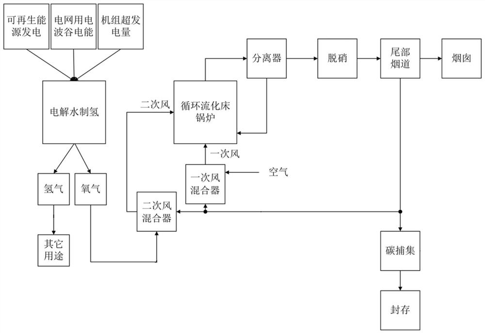
[0061] A process for hydrogen production from waste electricity combined with circulating fluidized bed boiler combustion, such as figure 1 As shown, the part of hydrogen production by electrolysis of water can use the abandoned electricity generated by solar photovoltaic or photothermal power generation during the day, and can use the cheap electricity during the power valley of the power grid at night to electrolyze water to produce hydrogen and oxygen. At the same time, during deep peak regulation Use the off-grid power generated by the unit itself to electrolyze water to produce hydrogen and oxygen. The hydrogen produced is used in hydrogen fuel cells, hydrogen-cooled generators, and other chemical industries. The oxygen obtained by the electrolysis of water can be mixed with the recirculated flue gas through the secondary air mixer and enter the circulating fluidized bed furnace as the secondary air, forming an oxidizing atmosphere in the upper part of the furnace, thereb...

Embodiment 2

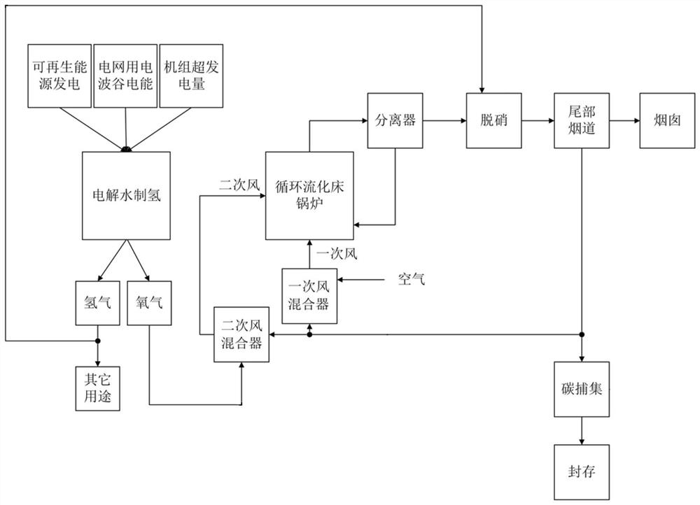
[0064] A process for hydrogen production from waste electricity combined with circulating fluidized bed boiler combustion, such as figure 2 As shown, the part of hydrogen production by electrolysis of water can use the abandoned electricity generated by solar photovoltaic or photothermal power generation during the day, and can use the cheap electricity during the power valley of the power grid at night to electrolyze water to produce hydrogen and oxygen. At the same time, during deep peak regulation Use the off-grid power generated by the unit itself to electrolyze water to produce hydrogen and oxygen. Part of the produced hydrogen is used for hydrogen fuel cells, hydrogen-cooled generators, and other chemical industries, and the other part is used for flue gas denitrification. The oxygen obtained by the electrolysis of water can be mixed with the recirculated flue gas through the secondary air mixer and enter the circulating fluidized bed furnace as the secondary air, formi...


PUM


Abstract

The invention discloses a process and a system for combining waste electricity hydrogen production with circulating fluidized bed boiler combustion. During deep peak regulation, a part of flue gas is used as circulating flue gas, a part of circulating flue gas is mixed with air or oxygen to obtain primary air, the primary air is used as fluidizing air to enter a hearth from the lower part of the hearth, the other part of circulating flue gas is mixed with oxygen to obtain secondary air, and the secondary air is fed into the hearth from the upper part of the hearth; the oxygen content in the primary air is lower than that in the air, and the oxygen content in the secondary air is higher than that in the air; the oxygen for mixing comes from a water electrolysis hydrogen production process; and in the water electrolysis hydrogen production process, waste electricity is adopted for water electrolysis hydrogen production. By means of the process and system, the problems that in-furnace fluidization safety is poor when the circulating fluidized bed unit is subjected to deep peak regulation, the original generation amount of in-furnace nitric oxide is increased, and the concentration of carbon dioxide in flue gas is low can be effectively solved, and therefore the deep peak regulation capacity of the circulating fluidized bed boiler generator unit is improved.

Description

technical field [0001] The invention relates to a process and system for producing hydrogen from waste electricity combined with circulating fluidized bed boiler combustion. Background technique [0002] The information disclosed in this background section is only intended to increase the understanding of the general background of the present invention, and is not necessarily taken as an acknowledgment or any form of suggestion that the information constitutes the prior art already known to those skilled in the art. [0003] Hydrogen energy has been widely used as a promising clean energy. Hydrogen production by electrolysis of water can produce extremely high-purity hydrogen. However, the cost of electricity consumption accounts for as high as 70-80% of the cost of hydrogen production. to a decisive role. Based on the above reasons, the use of waste electricity generated by renewable energy for hydrogen production by electrolysis of water has become a low-cost option for h...

Claims


Application Information

Patent Timeline
IPC IPC(8): F22B33/18F23L7/00F23L1/00F23L9/00F23J15/02C25B1/04C25B9/00C25B9/65C07C1/12C07C9/04C07C29/151C07C31/04
CPCF22B33/18F23L7/007F23L1/00F23L9/00F23J15/02C25B1/04C25B9/00C07C1/12C07C29/151F23L2900/07001C07C9/04C07C31/04Y02P20/50Y02P20/133Y02E60/36Y02E20/34Y02E20/32
Inventor 张缦冯玉鹏孔皓苗苗任帅张双铭杨海瑞
Owner TSINGHUA UNIV
Learn More