Balloon system and vascular calcification treatment device

A technology of balloons and catheters, which is applied in medical science, surgery, parts of surgical instruments, etc., and can solve problems such as poor therapeutic effect

Active Publication Date: 2021-08-24
HARBIN MEDICAL UNIVERSITY +1
View PDF7 Cites 1 Cited by
  • Summary
  • Abstract
  • Description
  • Claims
  • Application Information

AI Technical Summary

Problems solved by technology

[0004] In order to solve the problem in the prior art that the shock wave balloon has poor therapeutic effect when the bl

Method used


Image

  • Balloon system and vascular calcification treatment device
  • Balloon system and vascular calcification treatment device
  • Balloon system and vascular calcification treatment device

Examples


Embodiment 1

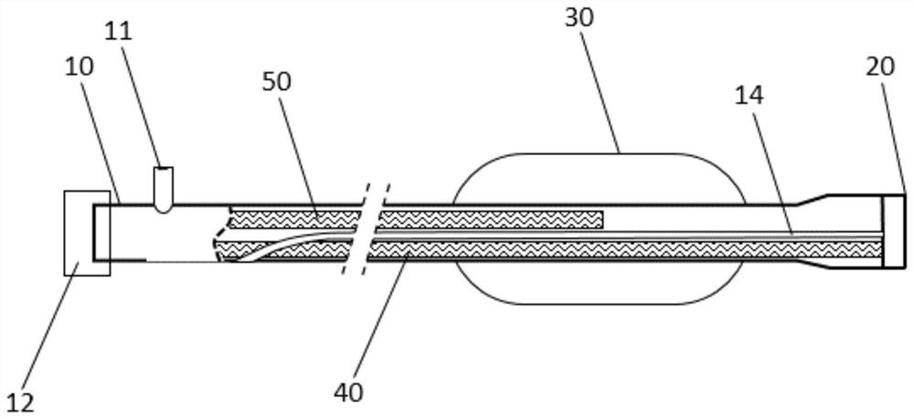
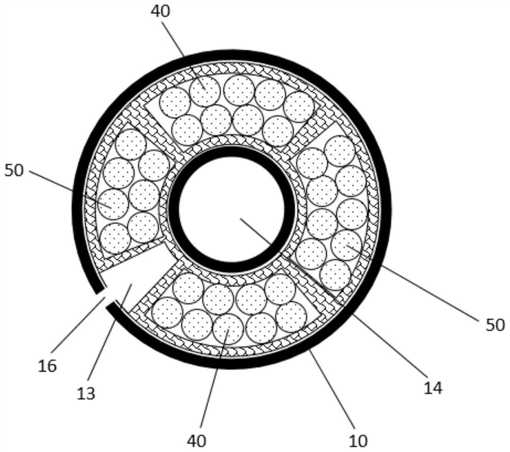
[0046] Please also refer to Figure 1 to Figure 4 , the present embodiment provides a balloon system, specifically a laser-induced shock wave balloon system, for treating vascular calcified lesions, especially calcified lesions occurring in coronary arteries. The balloon system includes a catheter 10, a beam expander 20, a balloon 30, a first fiber bundle 40 and a second fiber bundle 50, wherein the catheter 10 is used as a carrier and a support structure, and the first fiber bundle 40 and the second fiber bundle 50 are both placed inside the conduit 10. The beam expander 20 is connected to one end of the catheter 10 and cooperates with the first optical fiber bundle 40 to perform forward ablation of the calcified tissue. The balloon 30 is sheathed on the catheter 10 and adjacent to the beam expander 20, and cooperates with the second optical fiber bundle 50 to treat lateral calcification.

[0047]Specifically, a guide wire channel 14 is provided in the catheter 10 for passi...

Embodiment 2

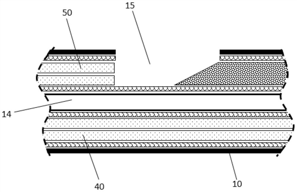
[0056] Please also refer to Figure 5 to Figure 11 , the present embodiment provides a balloon system, specifically a laser-induced shock wave balloon system, for treating vascular calcified lesions, especially calcified lesions occurring in coronary arteries. The balloon system includes a catheter 10 , a beam expander 20 , a balloon 30 , a first fiber optic bundle 40 and a second fiber optic bundle 50 . The catheter 10 serves as a carrier and a supporting structure, and the first optical fiber bundle 40 and the second optical fiber bundle 50 are both disposed inside the catheter 10 . The beam expander 20 is connected to one end of the catheter 10 and cooperates with the first optical fiber bundle 40 to perform forward ablation of the calcified tissue. The balloon 30 is sheathed on the catheter 10 and adjacent to the beam expander 20, and cooperates with the second optical fiber bundle 50 to treat lateral calcification.

[0057] Specifically, a guide wire channel 14 is provi...


PUM

PropertyMeasurementUnit
Shaft lengthaaaaaaaaaa
Lengthaaaaaaaaaa
Outer diameteraaaaaaaaaa

Abstract

The invention provides a balloon system and a vascular calcification treatment device, the balloon system comprises a catheter, one end of the catheter is provided with a beam expander, the other end of the catheter is provided with an injection interface and a laser interface, the catheter is sleeved with a balloon, and the catheter is internally provided with a first optical fiber bundle, a second optical fiber bundle, a balloon pressurizing channel and a guide wire channel; two ends of the first optical fiber bundle are respectively connected with the laser interface and the beam expander; one end of the balloon pressurizing channel is communicated with the injection interface, and the other end of the balloon pressurizing channel is communicated with the balloon; a cavitation bubble groove is formed in the catheter and communicated with the balloon, one end of the second optical fiber bundle is connected with the laser interface, and the other end of the second optical fiber bundle is located on one side of the cavitation bubble groove. According to the balloon system, forward ablation and lateral calcified tissue treatment are completed on one catheter at the same time, the operation time of doctors is shortened, and the treatment cost of the doctors is reduced.

Description

technical field [0001] The invention relates to the field of vascular calcification diagnosis and treatment equipment, in particular to a balloon system and a vascular calcification treatment device. Background technique [0002] The development of interventional diagnosis and treatment equipment for coronary heart disease has promoted the continuous improvement of the level of interventional diagnosis and treatment of coronary heart disease. Coronary lesions that previously required surgical thoracotomy (such as chronic occlusive lesions and severe calcified lesions) have corresponding devices to assist intervention treat. For severe calcified lesions, commonly used treatment methods include: shock wave balloon, cutting balloon, spinous process balloon, rotational milling or high pressure post-dilation and other techniques. [0003] For the situation of vascular calcification to complete occlusion, the treatment effect of the existing shock wave balloon is poor. Contents...

Claims


Application Information

Patent Timeline
IPC IPC(8): A61B18/22
CPCA61B18/22A61B2018/0022A61B2018/0041
Inventor 于波康维贾海波候静波代建南邢磊徐晨阳
Owner HARBIN MEDICAL UNIVERSITY
Why Eureka
Try Eureka