Drying mechanical equipment for agricultural product storage

A technology for mechanical equipment and agricultural products, which is applied in the field of drying machinery and equipment for agricultural product storage, which can solve problems such as sticking to each other, agricultural products not moving, and inability to dry, and achieve the effects of accelerating drying, increasing storage time, and accelerating dehydration

Active Publication Date: 2021-08-24
江苏瀚高科技有限公司
View PDF7 Cites 4 Cited by
  • Summary
  • Abstract
  • Description
  • Claims
  • Application Information

AI Technical Summary

Problems solved by technology

[0004] (1) When the existing dryer is drying the agricultural products, because the dryer only simply replaces the air, the drying speed of the agricultural products is relatively slow
[0005] (2) When the existing dryer is drying the agricultural products, the agricultural products that are piled up inside cannot be dried because the agricultural products remain still.
[0006] (3) When the existing dryers dry the agricultural products, they often turn the agricultural products manually at regular intervals, which is costly and labor-intensive
[0007] When the existing dryer is drying agricultural products, agricultural products with high humidity will stick to each other, making it impossible to dry

Method used


Image

  • Drying mechanical equipment for agricultural product storage
  • Drying mechanical equipment for agricultural product storage
  • Drying mechanical equipment for agricultural product storage

Examples


Embodiment 1

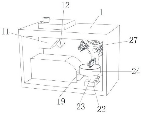
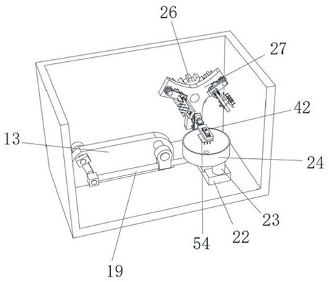
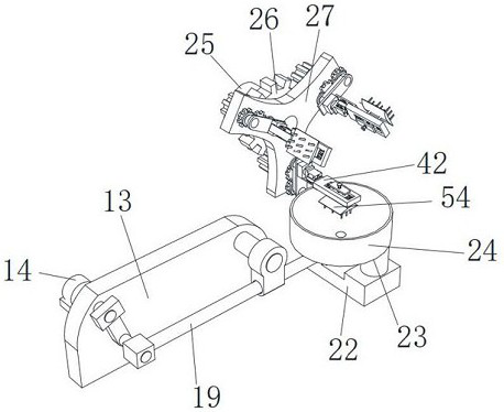
[0038] combine figure 1 , figure 2 , image 3 , Figure 4 , Image 6 and Figure 9 , a kind of drying mechanical equipment used for storing agricultural products, comprising a drying box 1, a drying machine assembly 11 is fixedly installed in the drying box 1, an air outlet pipe 12 is fixedly installed on the drying machine assembly 11, and the drying box 1 is provided with The gear-turning device, the shoveling device and the shoveling device, the shoveling device is on the shoveling device, the shoveling device is below the shoveling device, the gear-turning device includes a motor two 25, and the main gear is fixedly installed on the output shaft of the motor two 25 26, triangular plate 27 is fixedly installed on the output shaft of motor two 25, and the end of triangular plate 27 is fixedly installed with pinion two 3, and the inner side wall of triangular plate 27 horizontally rotates and is installed with rotating rod three 29, and the end of rotating rod three 29 i...

Embodiment 2

[0041] Building on Example 1: Combining figure 1 , figure 2 , image 3 , Figure 4 , Image 6 and Figure 8 The shovel device includes a rear insertion mechanism and a front insertion mechanism. The rear insertion mechanism includes a main support 38, and the end of the main support 38 is fixedly equipped with a rotating rod 5 34. The main support 38 is provided with a T-shaped chute 4, and the T-shaped slide The slot 4 is provided with two sockets one 39, the end of the main bracket 38 is fixedly equipped with a plunger 44, and the two sockets one 39 are horizontally slidably connected with a C-shaped plunger 41, and the C-shaped plunger 41 and the A miniature spring 43 is fixedly installed between the main brackets 38 , a rubber plate 45 is installed on the inner wall of the insertion rod 44 , and a miniature spring 2 46 is fixedly installed between the rubber plate 45 and the insertion rod 44 .

[0042] When in use, when the main bracket 38 drives the side bracket 5 t...

Embodiment 3

[0044] Building on Example 1: Combining figure 1 , figure 2 , image 3 , Figure 4 , Image 6 and Figure 7 , the front insertion mechanism includes a side bracket 5, a cross board 48 is fixedly installed on the side bracket 5, and two jacks 49 are run through on the cross board 48, and the end of the side bracket 5 is provided with a slot 47, and the side bracket 5 is fixedly installed with an auxiliary bracket 42, the auxiliary bracket 42 is provided with a chute 51, the cross plate 48 is inserted into the T-shaped chute 4, the insertion rod 44 is inserted into the slot 47, and the C-shaped insertion Rod 41 is inserted between two jacks 2 49 and 1 jack 39, rubber plate 45 fits with the end of side bracket 5, and connecting frame 52 is installed on auxiliary bracket 42, and connecting frame 52 is inserted in chute 51 , The end of connecting frame 52 is fixedly installed with connecting rod two 53, the end of connecting rod two 53 is fixedly installed with shoveling plat...


PUM


Abstract

The invention relates to the technical field of drying machinery, and discloses drying mechanical equipment for agricultural product storage. The drying mechanical equipment comprises a drying box, wherein a drying machine assembly is fixedly arranged in the drying box, and an air outlet pipe is fixedly arranged on the drying machine assembly; a turning gear device, a shovel shifting device and an anti-swing device are arranged on the drying box, the shovel shifting device is arranged on the turning gear device, and the anti-swing device is arranged below the shovel shifting device; and the turning gear device comprises a motor II. A C-shaped inserting rod is pulled out of a main support, the C-shaped inserting rod moves to drive a micro spring I to be pulled and deformed, and meanwhile the C-shaped inserting rod leaves an inserting hole I and an inserting hole II. At the moment, a user can integrally pull an auxiliary support to leave the main support, the auxiliary support moves to drive a side support to move, and the side support moves to drive a cross-shaped inserting plate to slide in a T-shaped sliding groove and drive an inserting groove to leave the inserting rod at the same time. The auxiliary support is independently replaced, and the whole equipment does not need to be disassembled, so that the maintenance convenience of the equipment is improved, and the maintenance difficulty is reduced.

Description

technical field [0001] The invention relates to the technical field of drying machinery, in particular to a drying mechanical equipment used for storing agricultural products. Background technique [0002] Dryer refers to a mechanical device that uses thermal energy to reduce the moisture content of materials, and is used to dry objects. The dryer vaporizes and escapes the moisture in the material (generally refers to water or other volatile liquid components) by heating to obtain a solid material with a specified moisture content. The purpose of drying is to meet the needs of material use or further processing. [0003] For example, the Chinese patent discloses "a new treatment device for pharmaceutical pulverizing and drying machines", publication number: CN112856930A, by setting up the mutual cooperation between the cleaning device and the discharge port, thereby achieving the effect of cleaning completely, avoiding the existing When the treatment device of the new phar...

Claims


Application Information

Patent Timeline
Patent Type & Authority Applications(China)
IPC IPC(8): F26B11/14F26B21/00F26B25/00F26B25/04A23L3/40
CPCF26B11/14F26B21/004F26B25/002F26B25/04A23L3/40Y02P60/85
Inventor 王红军
Owner 江苏瀚高科技有限公司
Why Eureka
Try Eureka