
Portable transformer direct current resistance detection device and method

A technology of DC resistance and detection device, applied in the direction of measurement device, measurement device shell, measurement resistance/reactance/impedance, etc., can solve the problems of equipment end face collision or extrusion damage, affecting detection results, unstable current output, etc. Avoid collision or extrusion damage, improve detection efficiency, and ensure the effect of accuracy

Inactive Publication Date: 2021-08-27
WUHAN HANYUAN JIJI ELECTRIC POWER EQUIP
View PDF0 Cites 0 Cited by
  • Summary
  • Abstract
  • Description
  • Claims
  • Application Information

AI Technical Summary

Problems solved by technology

[0003] However, the existing DC resistance detection equipment generally needs to be connected to an external battery power supply or equipped with a generator for use. Not only is the operation troublesome, but the current output is unstable, which greatly interferes with the detection results; It is easy to infiltrate dust and stains, resulting in poor signal transmission and affecting the test results; in addition, many DC resistance testing devices are usually large in size, inconvenient to carry, and lack end-face protection. If the placement surface is uneven, the end face of the device is vulnerable collision or crush injury

Method used


Image

  • Portable transformer direct current resistance detection device and method
  • Portable transformer direct current resistance detection device and method
  • Portable transformer direct current resistance detection device and method

Examples


Embodiment Construction

[0036] see Figure 1-7 , in the embodiment of the present invention,

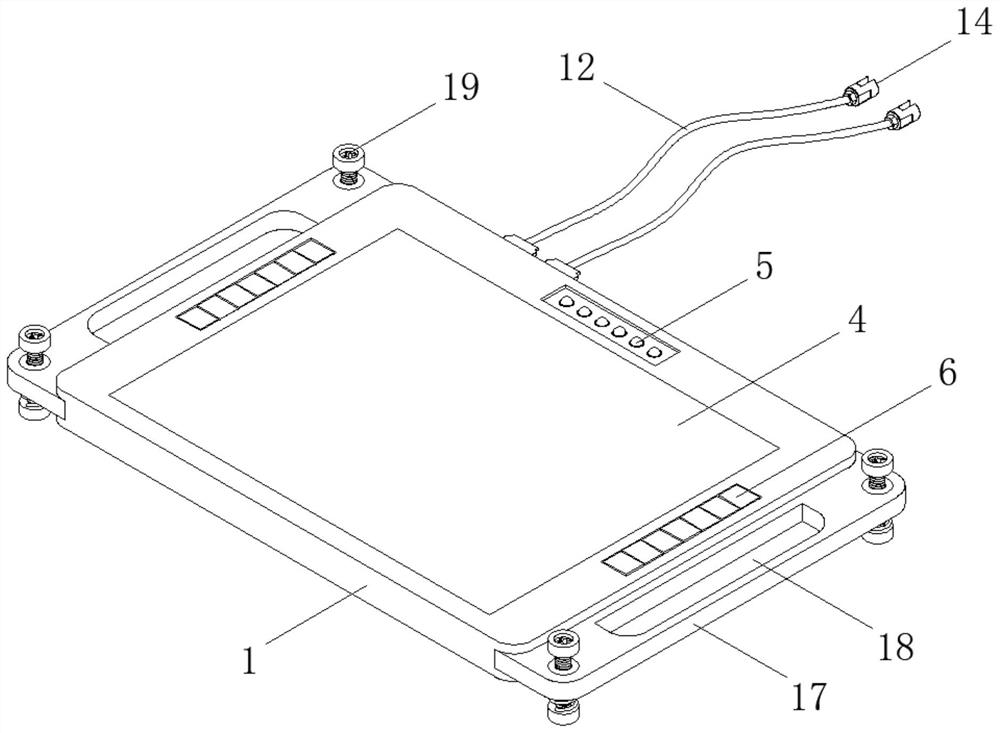
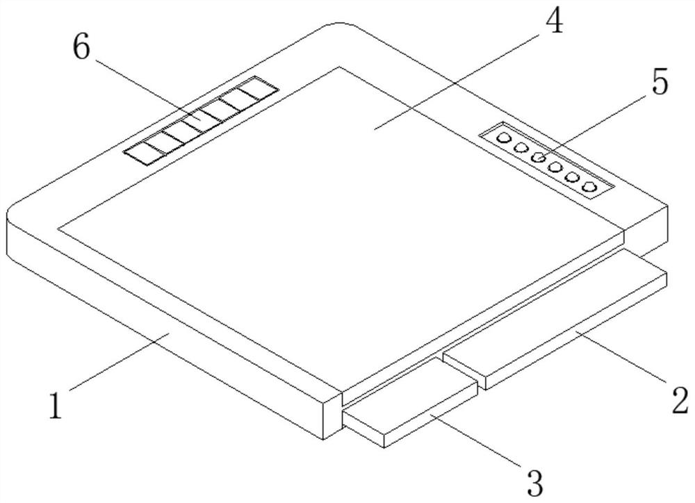
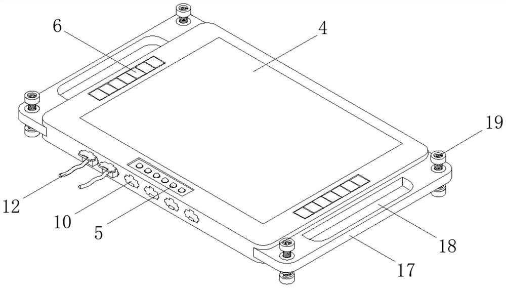
[0037] A portable transformer DC resistance detection device, comprising a housing 1, a PLC controller 2, an electrical connection terminal 14, a frame 17 and a support assembly 19, a PLC controller 2 is arranged inside one side of the housing 1, and the PLC controller 2- A lithium battery 3 is installed inside the housing 1 on one side, and a liquid crystal display 4 is inlaid on the other side of the housing 1, and several LED indicator lights 5 are installed at equal intervals on the outer wall of the housing 1 on one side of the liquid crystal display 4. Touch buttons 6 are installed on the outer walls of the housing 1 on the other two sides of the display screen 4;

[0038] A number of serial interfaces 7 are embedded at equal intervals on the side wall of the middle part of the housing 1, and one end of the data line 12 is inserted into the corresponding serial interface 7, and the other end of the d...


PUM


Abstract

The invention relates to the technical field of transformer detection, and discloses a portable transformer direct-current resistance detection device and method. The portable transformer direct-current resistance detection device comprises a shell, a PLC, power connection terminals, a frame and supporting assemblies, wherein the PLC is arranged in one side of the shell, a lithium battery is installed in the position, which is on one side of the PLC, of the shell, a liquid crystal display screen is embedded in the other side of the shell, the other ends of the data lines are movably connected with the power connection terminals through fastening nuts, and the supporting assemblies are vertically arranged on the two sides of the frame. The measurement process is short in time and high in speed, compared with a bridge measurement method, a lot of time is saved, the detection efficiency is greatly improved, a rubber blocking piece capable of being rotationally opened and closed is arranged at a serial interface, stains are prevented from permeating into the serial interface, the accuracy during electric signal switching is guaranteed, a bidirectional elastic supporting structure is further arranged, and collision or extrusion damage is avoided.

Description

technical field [0001] The invention relates to the technical field of transformer detection, in particular to a portable transformer DC resistance detection device and method. Background technique [0002] At present, the DC resistance measurement methods of power transformers are generally divided into three types: voltage current method, balanced bridge method, and DC resistance test method. Among them, the balanced bridge method and the DC resistance method are the main test methods, and the power supply methods are divided into AC 220V power supply and lithium battery power supply. [0003] However, the existing DC resistance detection equipment generally needs to be connected to an external battery power supply or equipped with a generator for use. Not only is the operation troublesome, but the current output is unstable, which greatly interferes with the detection results; It is easy to infiltrate dust and stains, resulting in poor signal transmission and affecting t...

Claims


Application Information

Patent Timeline
Patent Type & Authority Applications(China)
IPC IPC(8): G01R27/08G01R1/28G01R1/04G05B19/05
CPCG01R1/04G01R1/0408G01R1/28G01R27/08G05B19/054
Inventor 李苑曹胜祥罗超
Owner WUHAN HANYUAN JIJI ELECTRIC POWER EQUIP
Learn More