Electric energy transmitting and receiving system based on friction nano-generators
A nano-generator, transceiver system technology, applied in triboelectric generators, induction generators, battery circuit devices, etc., can solve problems such as large installation space, limited application range, high driving frequency, etc., to reduce output voltage and improve output. performance effect
- Summary
- Abstract
- Description
- Claims
- Application Information
AI Technical Summary
Problems solved by technology
Method used
Image

Examples
Embodiment Construction
[0030] In order to make the object, technical solution and advantages of the present invention clearer, the present invention will be further described in detail below in conjunction with the accompanying drawings and embodiments. It should be understood that the specific embodiments described here are only used to explain the present invention, and do not limit the protection scope of the present invention.
[0031] In order to better understand the present invention, an application example of a triboelectric nanogenerator-based power transceiving system proposed by the present invention will be described in detail below.
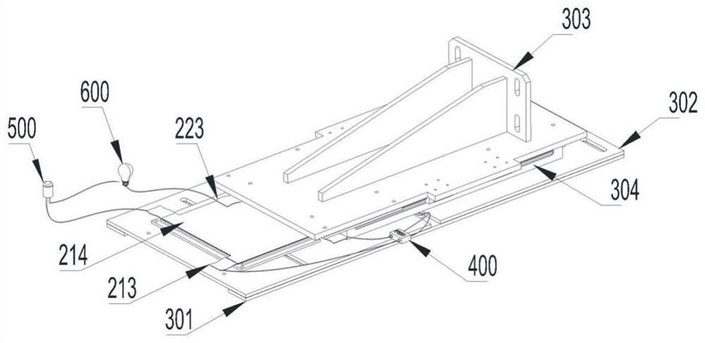
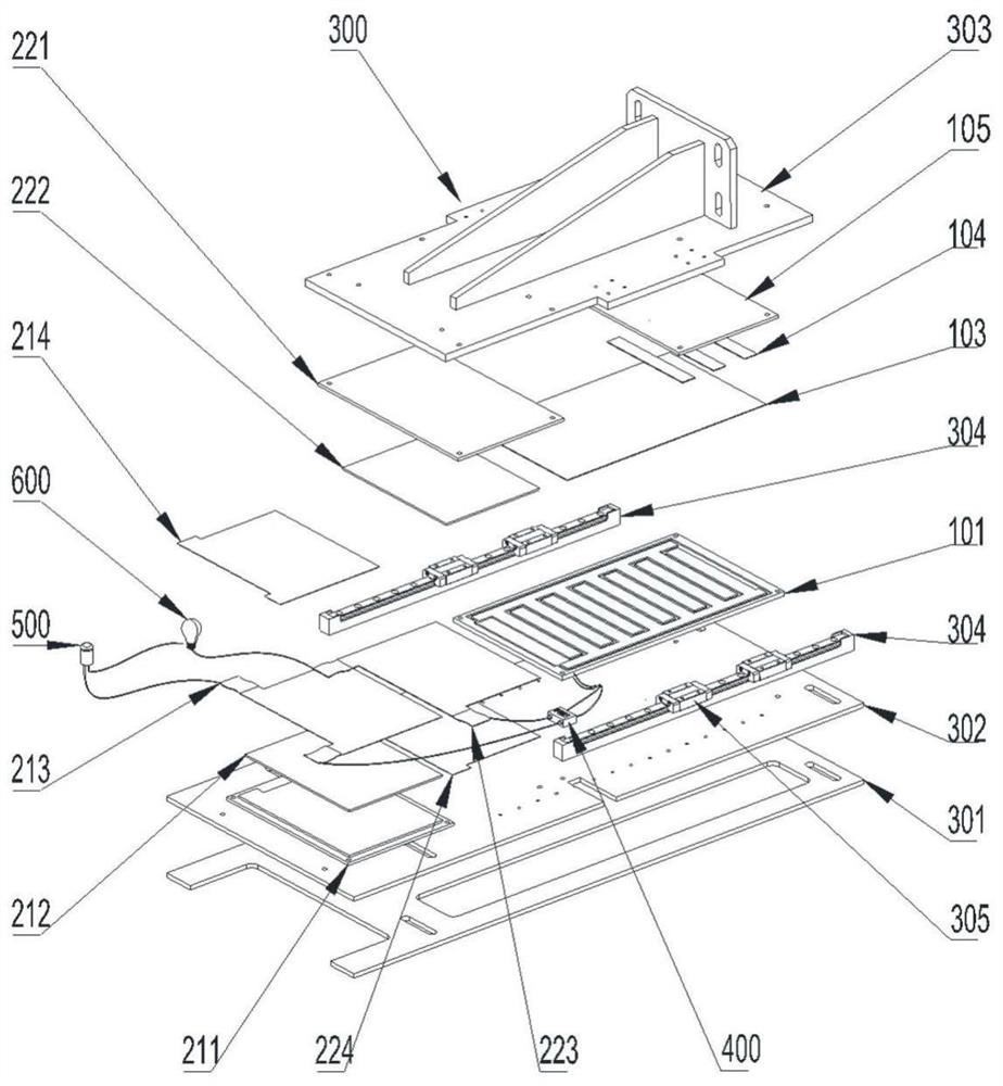
[0032] see Figure 1~3 , a frictional nanogenerator-based power transceiving system according to an embodiment of the present invention includes a drive assembly 300, and the first frictional nanogenerator 100 and the second frictional nanogenerator 200 driven by the drive assembly 300 are connected to the first frictional nanogenerator The circuit managem...
PUM
 Abstract
Description
Claims
Application Information