Water cooling plate

A water-cooled plate and water-cooled technology, which is applied in the cooling combination arrangement of power units, electric vehicles, battery/fuel cell control devices, etc., can solve the problems of high tooling cost, high comprehensive cost and high cost, and achieve low mold cost, The effect of low comprehensive cost and high flexibility

Pending Publication Date: 2021-08-31
东时(武汉)新能源科技有限公司
View PDF0 Cites 0 Cited by
  • Summary
  • Abstract
  • Description
  • Claims
  • Application Information

AI Technical Summary

Problems solved by technology

However, the harmonica tube type has a single flow channel, small contact area, and thin pipe wall, which leads to its general heat transfer effect and poor load-bearing capacity; the stamping and brazing type requires high tooling costs due to the need to open stamping molds, and the brazing furnace The equipment cost is high, the comprehensive cost is high, and each battery has to be invested separately, which is not universal; the parallel flow tube structure is complex, and it is in direct contact with the battery cell, which not only has high requirements for the BMS control system, but also has high cost. It has versatility; the machine plus box type uses CNC milling grooves to form the flow channel, which is high in cost and low in efficiency, and does not have versatility; the pressure tube type is a structure in which bent copper tubes are pressed into the flow channel, which is costly and expensive. Single, not universal

Method used


Image

  • Water cooling plate
  • Water cooling plate
  • Water cooling plate

Examples


Embodiment 1

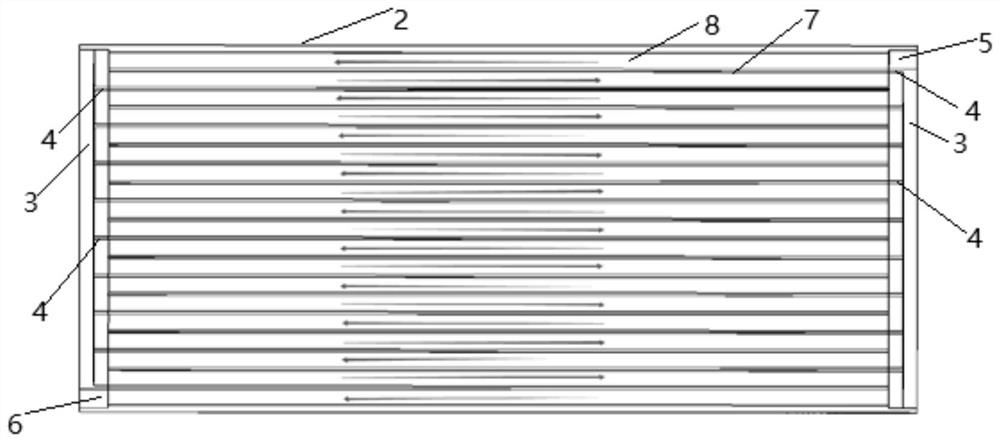
[0053] like figure 2 As shown, the number of plugs 4 on the two side panels 3 of this water cooling portion 1 is the same, and a split plate 7 is disposed at a time separation plate 7 is provided, and one end of any of the buses 7 is fixed to the plug 4. Connection, the other end does not set the plug 4, where one end of the splitter plate 7 adjacent the inlet hole 5 is fixed to the plug 4, that is, the cooling water is blocked from the inlet hole 5 after the blocking of the plug 4 will only flow to the first A split portion 8 and the plug 4 on the second shunting plate 7 blocks flow to the second shunt portion 8, so that the cooling water is circulated in the plurality of shunt portions 8, corresponding to the water-cooled portion 1 The position of the battery is sequentially dissipated.

Embodiment 2

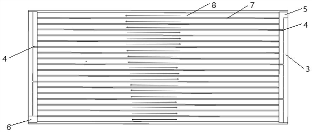
[0055] The number of plugs 4 on the two side panels 3 of this water cooling portion 1 and the position of the setting, such as image 3 As shown in the three adjacent shunt portions 8 as a set, the cooling water flows from the inlet hole 5 to the three adjacent shunt portions 8, and flows at the same time after reaching the next set of shunt portions 8 In the three shunt portions 8 of the next group, i.e., the water-cooled portion 1 can heat dissipate the position of the corresponding battery on the three adjacent shunt portions at the same time, and the heat dissipation area is more good.

[0056] In another technical solution, the plug 4 of the adjacent two water-cooled portions 1 is the same or different.

[0057] In the present technical solution, since the number of plugs 4 on the water-cooled portion 1 affects its heat dissipation effect, that is, the position of the cell corresponding to the adjacent two water-cooled portion 1 on the water cooled plate. The heat dissipation ...


PUM


Abstract

The invention discloses a water cooling plate which comprises a plurality of water cooling parts arranged continuously, the adjacent water cooling parts are fixedly connected, and any water cooling part comprises a plate body which is of a hollow box body structure with openings in the two ends; two side plates which are oppositely arranged at the two ends of the plate body, wherein a sealed water cooling cavity is formed by the two side plates and the plate body; a plurality of shunting plates which divide the water cooling cavity into a plurality of shunting parts which are communicated with one another; two plug groups which are respectively arranged on the two side plates, wherein any plug group comprises a plurality of plugs which are arranged at intervals along the width direction of the plate body, and any plug is arranged between the side plate and the adjacent splitter plate. The number of the water cooling parts is selected according to different battery lengths, so that the length of the water cooling plate is matched with the length of the battery needing heat dissipation, the flexibility is high, and the circulation path and the water flow direction of cooling water are changed by adjusting the number of the plugs in the water cooling parts and the arranged positions, so that the heat dissipation effect of the water cooling plate is adjusted.

Description

Technical field [0001] The present invention relates to the field of water-cooled plate. More particularly, the present invention relates to a water-cooled plate. Background technique [0002] With the continued increase in car ownership in my country, the energy shortage and environmental pollution problems resulting increasingly prominent. Therefore, my country's vigorous promotion of new energy vehicles, which focuses on the development of electric vehicles. [0003] Battery power is one of the key components of electric vehicles, and therefore battery technologies for electric vehicles is very important. As the market for electric vehicles battery life, charge and discharge performance requirements higher and higher, the thermal management system requires power battery systems are also more stringent. In mature cooling in air in addition to other heat transfer means used in conjunction with an outer, substantially has excluded the application scope of the battery pack passeng...

Claims


Application Information

Patent Timeline
Patent Type & Authority Applications(China)
IPC IPC(8): B60K1/00B60K11/04B60L58/26H01M10/613H01M10/625H01M10/6554H01M10/6556H01M10/6567
CPCB60K1/00B60K11/04B60K2001/005B60L58/26H01M10/613H01M10/625H01M10/6554H01M10/6556H01M10/6567Y02E60/10Y02T10/70
Inventor 方锳泽龙曲波肖伟杨宇王宇威廖洋
Owner 东时(武汉)新能源科技有限公司
Why Eureka
Try Eureka