
Spot welding robot operation space smooth path planning method for curved surface workpiece

A technology for path planning and surface workpieces, which is applied in instruments, digital control, control/regulation systems, etc., and can solve problems such as the inability to obtain the global optimal solution of the welding path.

Active Publication Date: 2021-08-31
CHANGCHUN UNIV OF TECH +1
View PDF4 Cites 2 Cited by
  • Summary
  • Abstract
  • Description
  • Claims
  • Application Information

AI Technical Summary

Problems solved by technology

The problem of welding path between solder joints and the problem of welding sequence of solder joints are relatively independent, and the optimization process is interdependent. However, most of the existing methods only consider the welding sequence of solder joints, and cannot obtain the overall situation of the welding path in the operation space. Optimal solution

Method used


Image

  • Spot welding robot operation space smooth path planning method for curved surface workpiece
  • Spot welding robot operation space smooth path planning method for curved surface workpiece
  • Spot welding robot operation space smooth path planning method for curved surface workpiece

Examples


Embodiment Construction

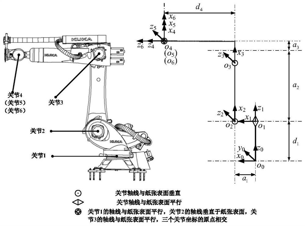
[0021] Attached below Figure 1-15 The present invention is described in further detail,

[0022] Such as figure 1 As shown, the transformation matrix of the robot link is as follows:

[0023]

[0024] In the formula, a i-1 is the connecting rod length, α i-1 is the connecting rod twist angle, d i is the connecting rod offset, θ i is the joint angle. cθ i represents cosθ i , sθ i Indicates sinθ i , cα i-1 means cosα i-1 , sα i-1 Indicates sinα i-1 .

[0025] due to a i-1 、α i-1 、d i are known quantities, so the joint transformation matrix Only with the joint variable θ i Relevant, therefore, the following formulas, unless otherwise specified, c i represents cosθ i ,s i Indicates sinθ i .

[0026] The pose of the end coordinate system of the robot in the base coordinates is described by a homogeneous transformation matrix, and the positive solution expression of the robot kinematics is:

[0027]

[0028] In the formula, θ includes (θ 1 ,θ 2 ,θ ...


PUM


Abstract

The invention discloses a spot welding robot operation space smooth path planning method for a curved surface workpiece. In the method, a spot welding robot kinematic model module, a motion constraint condition module, an inter-welding-spot shortest smooth obstacle avoidance path planning module and an optimal welding spot welding sequence planning module are included. The method is characterized by modeling through a three-dimensional grid method curved surface workpiece profile and welding spot distribution, adopting an improved A-star algorithm and a uniform B spline curve subdivision algorithm for smooth processing to generate an inter-welding-spot shortest smooth obstacle avoidance path, and applying a multi-target elite simulated annealing genetic algorithm to obtain an optimal welding sequence; and according to the collision-free motion constraint conditions of an electrode holder coordinate system and a welding spot coordinate system and the safe distance constraint conditions of the electrode holder coordinate system and a curved surface workpiece profile, solving through inverse kinematics to obtain a joint space path corresponding to the current welding path. The method has an application reference value in the actual industry, the planning and debugging time of an engineer can be shortened, and the working efficiency of a robot can also be improved.

Description

technical field [0001] The invention relates to the technical field of robot welding, in particular to a method for planning a smooth path in the operating space of a spot welding robot for curved surface workpieces. Background technique [0002] The automotive industry is a typical application field of the spot welding robot system, and about 60% of the car body welding points are completed by robots. Due to the complex shape of the workpiece and the distribution of solder joints, the spot welding robot reasonably arranges the welding sequence of these solder joints and obtains an excellent welding trajectory planning scheme, which is of great significance for saving welding time, reducing production costs and improving production efficiency. At present, there is still a lot of room for robot application research. Welding engineers often rely on their own experience, plus referring to the designer's process card, relying on the long-term teaching and debugging of the teachi...

Claims


Application Information

Patent Timeline
Patent Type & Authority Applications(China)
IPC IPC(8): G05B19/19
CPCG05B19/19G05B2219/35349
Inventor 张邦成赵航尹晓静柳虹亮杨磊孙建伟常笑鹏陈司昱邵昱博张子强夏奇
Owner CHANGCHUN UNIV OF TECH
Learn More