
Automatic clamping device of mechanical polishing equipment

A technology of mechanical polishing and clamping device, which is applied in the direction of grinding/polishing equipment, grinding drive device, surface polishing machine tool, etc. It can solve the problem of indetermination of product qualification, affecting the production efficiency and aesthetics of metal handles, and polishing device Problems such as inability to detect surface flatness

Active Publication Date: 2021-09-03
江门美壳制冷设备有限公司
View PDF13 Cites 3 Cited by
  • Summary
  • Abstract
  • Description
  • Claims
  • Application Information

AI Technical Summary

Problems solved by technology

[0005] In order to overcome the prior art when polishing the metal door handle, the thin metal sheet of the metal handle will be bent and curled, which seriously affects the applicability of the metal handle; the traditional clamping device cannot realize the polishing of the inner surface of the metal handle , the handle needs to be removed and manually polished to achieve the polishing of the inner surface; it seriously affects the production efficiency and aesthetics of the metal handle; and the existing polishing device cannot detect the smoothness of the polished surface, and cannot determine the qualification of the product However, the technical problem to be solved by the present invention is to provide an automatic clamping device for mechanical polishing equipment

Method used


Image

  • Automatic clamping device of mechanical polishing equipment
  • Automatic clamping device of mechanical polishing equipment
  • Automatic clamping device of mechanical polishing equipment

Examples


Embodiment 1

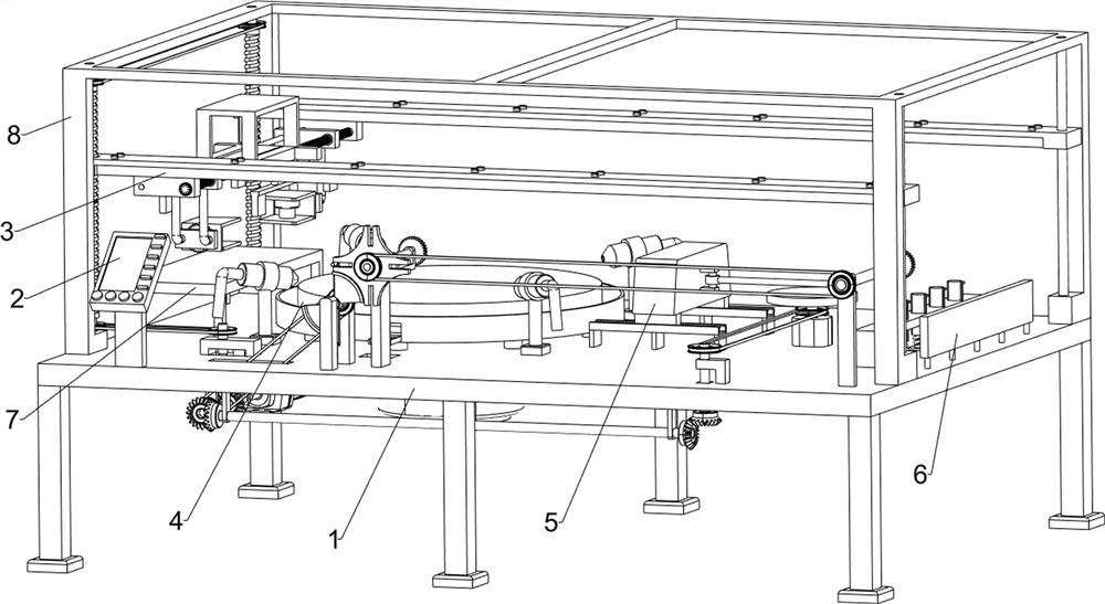
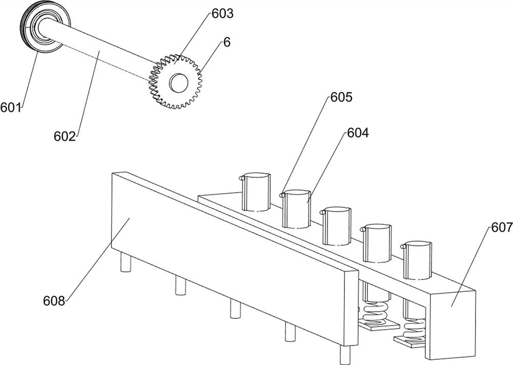
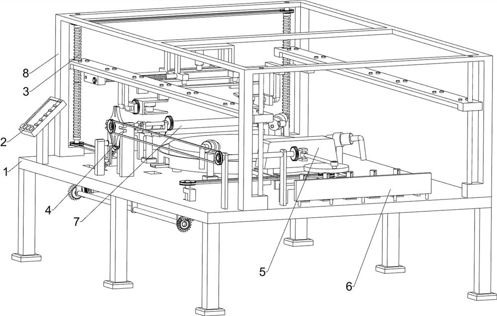
[0034] An automatic clamping device for mechanical polishing equipment, such as Figure 1-11 As shown, it includes a support base plate 1, a control panel 2, a clamping and conveying system 3, an outer surface polishing system 4, an inner arc surface polishing system 5, a detection system 6, a stage 7 and a fixing frame 8; the support base plate 1 and the control The screen 2 is connected; the support base 1 is connected with the outer surface polishing system 4, the inner arc surface polishing system 5 and the detection system 6 in sequence; the support base 1 is connected with the stage 7; the support base 1 is connected with the fixed frame 8; The outer surface polishing system 4 is connected with the inner arc surface polishing system 5 ; the outer surface polishing system 4 is connected with the detection system 6 .


PUM


Abstract

The invention relates to the field of machining, in particular to an automatic clamping device of mechanical polishing equipment. The technical problem to be solved is to provide the automatic clamping device of the mechanical polishing equipment. According to the technical scheme, the automatic clamping device of the mechanical polishing equipment comprises an outer surface polishing system; and the outer surface polishing system is connected with a detection system. According to the automatic clamping device of the mechanical polishing equipment, the problem that when a metal door handle is polished, the thin part of a metal sheet is bent and curled is solved, and the applicability of the metal handle is improved; meanwhile, the inner side face, which cannot be treated by a traditional clamping device, of the metal handle is polished, the situation that the inner side face needs to be polished in the mode that the handle is taken down for manual matched grinding is avoided, whole-process mechanical polishing is achieved, and the production efficiency and the attractiveness degree of the metal handle are improved; And the surface flatness of the polished part is detected, and the qualification of the product is determined.

Description

technical field [0001] The invention relates to the field of mechanical processing, in particular to an automatic clamping device of mechanical polishing equipment. Background technique [0002] Mechanical polishing relies on the grinding and rolling action of very fine polishing powder to remove a very thin layer of metal on the grinding surface of the sample; polishing can be used to enhance and restore the appearance of certain metal parts or against vehicles such as cars, handrails, Cookware, cookware and construction metals. [0003] When polishing the metal door handle in the prior art, the thin metal sheet of the metal handle will be bent and curled, which seriously affects the applicability of the metal handle; the traditional clamping device cannot realize the polishing of the inner surface of the metal handle, and needs The inner surface is polished by removing the handle and manually grinding it; it seriously affects the production efficiency and aesthetics of th...

Claims


Application Information

Patent Timeline
IPC IPC(8): B24B29/02B24B27/00B24B41/00B24B41/02B24B41/06B24B41/04B24B57/02B24B49/12B24B47/12
CPCB24B29/02B24B27/0076B24B27/0069B24B41/005B24B41/02B24B41/06B24B41/04B24B57/02B24B49/12B24B47/12Y02P70/10
Inventor 李瑞文
Owner 江门美壳制冷设备有限公司
Learn More