Perforating device for capacitor film machining

A capacitor film and punching device technology, which is applied in metal processing and other directions, can solve the problems of high cost and bloated mechanism, and achieve the effects of strong applicability, meeting the needs of use, and convenient use

Inactive Publication Date: 2021-09-03
东莞市普隆电子有限公司
View PDF5 Cites 0 Cited by
  • Summary
  • Abstract
  • Description
  • Claims
  • Application Information

AI Technical Summary

Problems solved by technology

[0004] The purpose of the present invention is to solve the problems of high cost and bloated mechanism in the prior art, and propose a punching device for capacitor film processing

Method used


Image

  • Perforating device for capacitor film machining
  • Perforating device for capacitor film machining
  • Perforating device for capacitor film machining

Examples


Embodiment 1

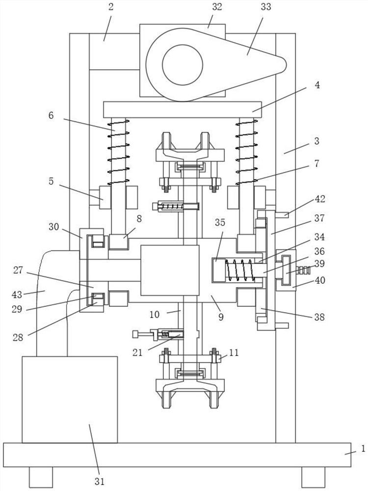
[0028] refer to Figure 1-4 , a punching device for capacitor film processing, comprising a base plate 1, two drum mounting rings 8 are arranged vertically above the base plate 1, and a center shaft cylinder 9 is arranged on a rotating frame between the two drum mounting rings 8, and the center shaft The outer side of the barrel 9 is divergently provided with several installation mechanisms, the end of the installation mechanism is detachably installed with a cutting assembly, the top of the central axis cylinder 9 is provided with a pressing assembly, one end of the central axis cylinder 9 is provided with a suction chamber, and the bottom plate A vacuum cleaner 31 is also installed on the top side of 1, and a connecting pipe 43 is installed on the vacuum cleaner 31. One end of the connecting pipe 43 communicates with the material suction chamber, and a fixing mechanism is arranged between the central axis cylinder 9 and the drum mounting ring 8;

[0029] Install the device o...

Embodiment 2

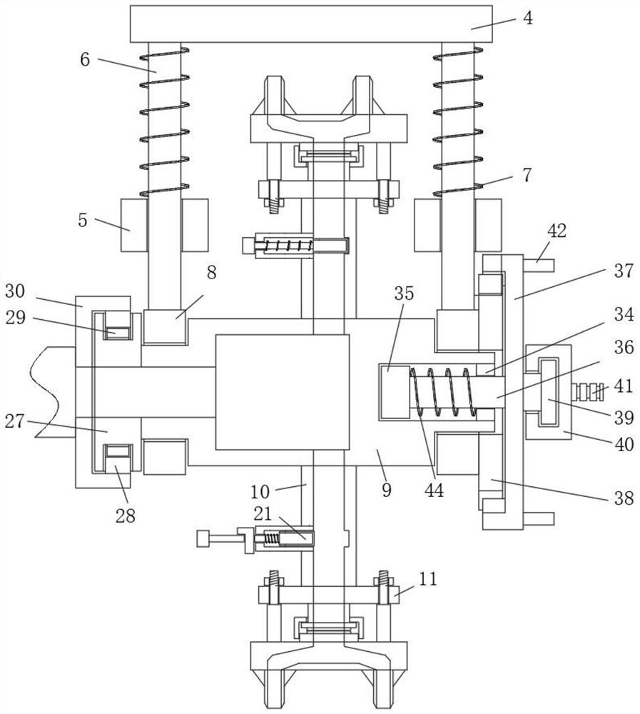
[0033] Such as Figure 1-4 As shown, this embodiment is basically the same as Embodiment 1. Preferably, the pressing down assembly includes a hanging plate 4 vertically above the bottom plate 1, and a motor mounting seat 2 is provided on the top side of the hanging plate 4, and the motor mounting seat 2 and the Support columns 3 are arranged between the bottom plates 1, and one side of the support columns 3 is fixedly connected with a rail vertical cylinder 5, and a rail sliding rod 6 slides through the rail vertical cylinder 5, and the top of the rail sliding rod 6 is fixed to the hanging plate 4. A spring 7 is arranged between the track vertical cylinder 5 and the hanging plate 4, the bottom end of the track slide bar 6 is fixed with the drum mounting ring 8, and a motor 32 is fixed on one side of the motor mounting seat 2 by bolts, and the output of the motor 32 A cam 33 is installed on the shaft, and the bottom of the cam 33 is connected in sliding contact with the top sid...

Embodiment 3

[0036] Such as Figure 1-4 As shown, this embodiment is basically the same as Embodiment 1. Preferably, the end of the central shaft cylinder 9 away from the connecting ring 27 is provided with a polygonal side groove and is slidably connected to a polygonal sliding core 35, and the inner wall of the opening of the polygonal side groove is fixedly connected. Position ring 34, a spring three 44 is arranged between the limit ring 34 and the polygonal sliding core 35, and one side of the polygonal sliding core 35 is fixedly connected with a connecting rod 36, and one end of the connecting rod 36 passes through and is fixed in the limiting ring 34 A safety tooth cover 37 is connected, and one side of the rotating cylinder installation ring 8 is fixedly connected with a safety tooth seat 38, and a circular groove is opened on one side of the safety tooth cover 37, and a tooth groove is provided on the inner wall of the circular groove and is engaged and sleeved on the safety tooth c...


PUM


Abstract

The invention discloses a perforating device for capacitor film machining. The perforating device comprises a bottom plate, two rotating cylinder mounting rings are arranged on the vertical upper side of the bottom plate, a middle shaft cylinder is rotationally erected between the two rotating cylinder mounting rings, a plurality of mounting mechanisms are arranged on the outer side of the middle shaft cylinder in a divergent mode, a cutting assembly is detachably mounted at the end of each mounting mechanism, a downward-pressing assembly is arranged at the top of the middle shaft cylinder, a suction cavity is formed in one end of the middle shaft cylinder, a dust collector is further mounted on the top side of the bottom plate, a communicating pipe is mounted on the dust collector, one end of the communicating pipe communicates with the suction cavity, a fixing mechanism is arranged between the middle shaft cylinder and each rotating cylinder mounting ring, and each mounting mechanism comprises a side pipe fixedly connected with the middle shaft cylinder. The perforating device is high in applicability, can meet the perforating requirements of different capacitor films, can collect waste materials in time, is convenient to use, is ingenious and stable in structure, reduces the production cost, and meets the use requirements of people in production and life.

Description

technical field [0001] The invention relates to the technical field of capacitor processing equipment, in particular to a punching device for capacitor film processing. Background technique [0002] There are many types of capacitors depending on the medium, such as: electrolytic capacitors, paper capacitors, film capacitors, ceramic capacitors, mica capacitors, air capacitors, etc. However, the most frequently used in audio equipment are electrolytic capacitors and film (Film) capacitors. Electrolytic capacitors are mostly used in places that require a large capacitance, such as the filter capacitor of the main power supply, which is used for storing electric energy in addition to filtering. Film capacitors are widely used in the cross-connection of analog signals and the bypass (reverse cross-connection) of power supply noise. Film capacitors are excellent capacitors due to their many excellent characteristics. Its main characteristics are as follows: non-polarity, high...

Claims


Application Information

Patent Timeline
Patent Type & Authority Applications(China)
IPC IPC(8): B26F1/04B26F1/14B26D7/18B26D7/26
CPCB26F1/04B26F1/14B26D7/1863B26D7/2628
Inventor 叶宝华张海波范鹏元姜礼
Owner 东莞市普隆电子有限公司
Why Eureka
Try Eureka