Special-shaped column and I-shaped steel beam connecting joint structure and joint safety monitoring method

A technology for connecting nodes and I-beams, applied in building components, measuring devices, instruments, etc., can solve problems such as hidden safety hazards, no real-time observation of deformation degree and alarm, damage to components at node connections, etc. The use of bolts, the avoidance of personal and property damage, the effect of strong bearing capacity and shear resistance

Active Publication Date: 2021-09-03
SHANDONG XINGHUA CONSTR GRP
View PDF9 Cites 0 Cited by
  • Summary
  • Abstract
  • Description
  • Claims
  • Application Information

AI Technical Summary

Problems solved by technology

The traditional special-shaped concrete-filled steel tube column-I-shaped steel beam rigid joints are mostly connected by a large number of bolts, which leads to damage to the components at the joint joints, and there are certain safety hazards, and most of these joints do not have the effect of reinforcing special-shaped steel tube concrete columns. And when the node structure is deformed, it does not have the function of real-time observation of deformation degree and alarm

Method used


Image

  • Special-shaped column and I-shaped steel beam connecting joint structure and joint safety monitoring method
  • Special-shaped column and I-shaped steel beam connecting joint structure and joint safety monitoring method
  • Special-shaped column and I-shaped steel beam connecting joint structure and joint safety monitoring method

Examples


Embodiment 1

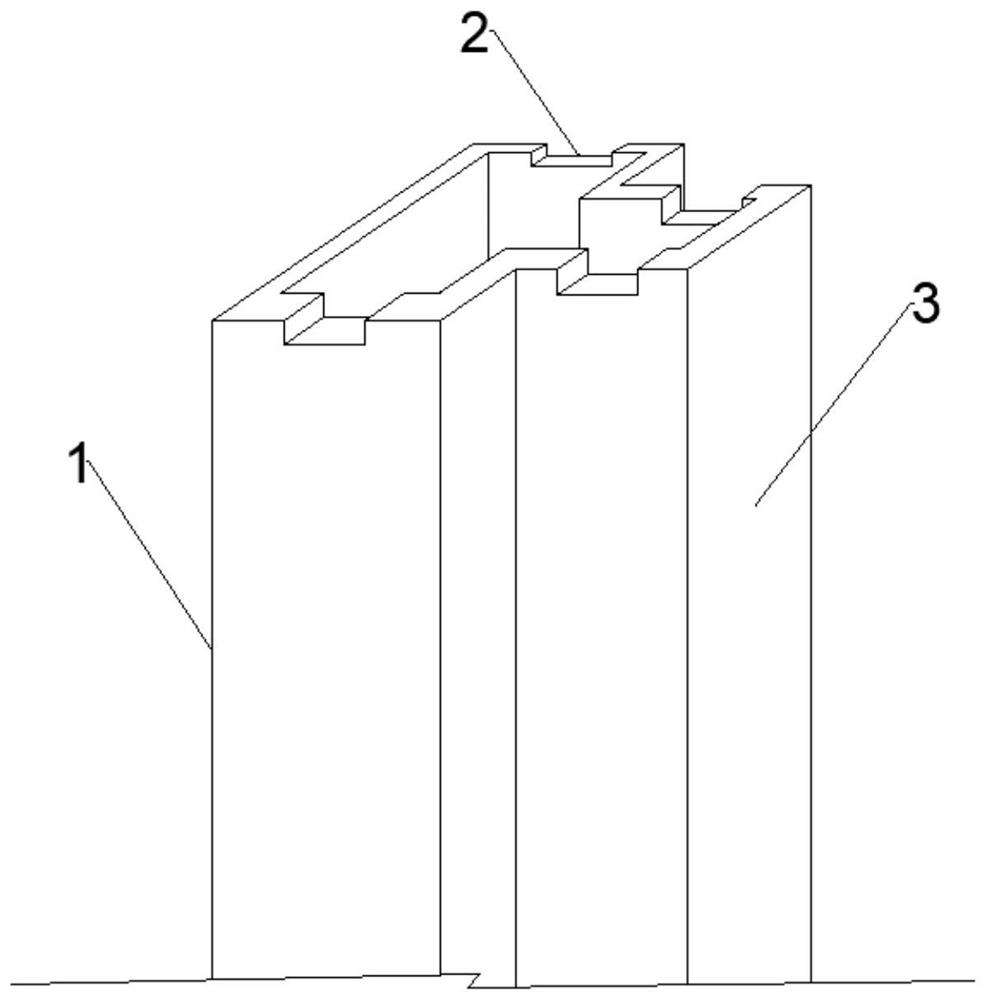
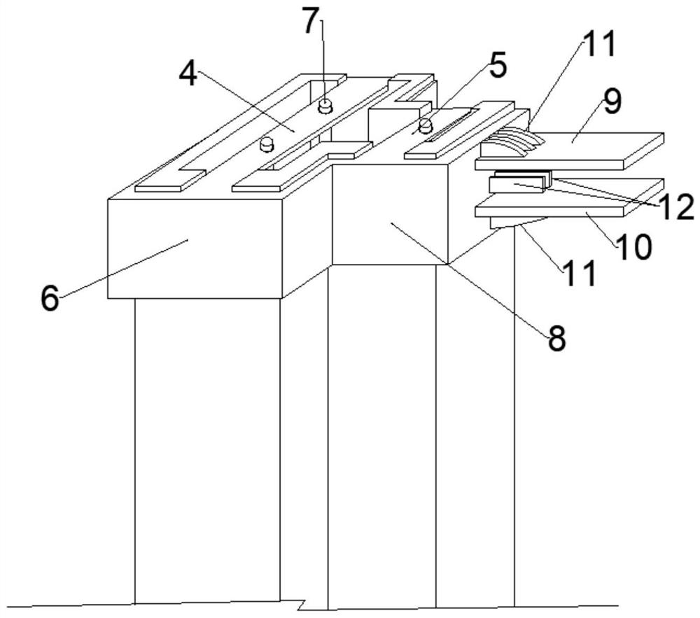
[0035] A connection node structure between concrete filled steel pipe special-shaped columns and I-shaped steel beams, such as figure 2 , 3 As shown, it includes a core special-shaped column 1, a transfer structure, and an I-shaped steel beam. Concrete is poured in the core special-shaped column 1, and a card slot 2 is provided at the top of the side wall of the core special-shaped column 1. One end of the connection structure is clamped on the top of the core special-shaped column, and the other end is detachably and fixedly connected to the end of the I-beam. The concrete is provided with prestressed steel bars 7, and the transfer structure is passed through the prestressed steel bars. 7 fixed along the longitudinal direction;

[0036] Such as figure 2 , 3As shown, the cross-section of the core special-shaped column 1 is a "T"-shaped structure, and the left end of the "T"-shaped structure and the top of the side wall of the protruding end 3 protruding to the right along...

Embodiment 2

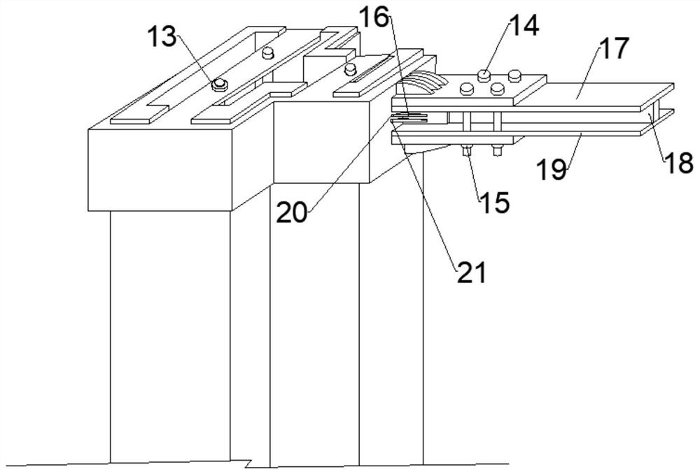
[0043] Such as figure 1 , 3 As shown, the vertical plates 12 are made of low-carbon steel, and two extruded plates 16 arranged in parallel up and down are respectively connected to the outer end surfaces of the two vertical plates 12, and the left ends of the extruded plates 16 protrude from the The right end surface of the end fastening plate 8 is clearance fit;

[0044] Such as figure 1 , 4 As shown, a first pressure sensor 20, a second pressure sensor 21, a third pressure sensor 22, and a fourth pressure sensor 23 are respectively provided on the right end surface of the protruding end fastening plate 8 opposite to the left end of the extrusion plate 16, The first pressure sensor 20, the second pressure sensor 21, the third pressure sensor 22, and the fourth pressure sensor 23 are electrically connected to a power supply, a display and an alarm by wires respectively. The third pressure sensor 22 is located at the top, and the second pressure sensor 21 and the fourth pre...

Embodiment 3

[0046] Such as figure 1 , 4 As shown, a method for monitoring and judging the safety status of the joint structure of the special-shaped steel pipe concrete column and the I-shaped steel beam connection structure, including:

[0047] A. When the first pressure sensor 20 and the third pressure sensor display the pressure value, while the pressure value of the fourth pressure sensor and the second pressure sensor 21 is 0, it means that the right end of the I-beam is upturned; otherwise, it means the I-shaped The right end of the steel beam droops.

[0048] B. When the first pressure sensor 20 and the second pressure sensor 21 display the pressure value, and the pressure value of the third pressure sensor and the fourth pressure sensor is 0, it means that the right end of the I-shaped steel beam is convex; otherwise, it represents the I-shaped The right end of the steel beam is kyphotic.

[0049] C. If the value of a certain pressure sensor is obviously greater than the value ...


PUM


Abstract

The invention discloses a special-shaped column and I-shaped steel beam connecting joint structure and a joint safety monitoring method, and relates to the technical field of constructional engineering connecting joints. The special-shaped column and I-shaped steel beam connecting joint structure comprises a core special-shaped column, an adapter structure and an I-shaped steel beam, concrete is poured in the core special-shaped column, and a clamping groove is formed in the top end of the side wall of the core special-shaped column; one end of the adapter structure is clamped at the top end of the core special-shaped column, the other end of the adapter structure is detachably and fixedly connected with the end part of the I-shaped steel beam, prestressed reinforcements are arranged in the concrete, and the adapter structure is fixed in the longitudinal direction through the prestressed reinforcements. According to a connecting joint, the using amount of bolts is reduced, and the joint is accurate in positioning and firm in connection. Through the joint safety monitoring method, deformation of the joint can be monitored in real time, and an alarm can be given in real time when the joint is damaged.

Description

technical field [0001] The invention relates to the technical field of connection nodes of construction engineering, in particular to a connection node structure between a special-shaped column and an I-shaped steel beam and a node safety monitoring method. Background technique [0002] In recent years, policies on the industrialization of steel structure buildings and prefabricated buildings have been introduced one after another, proposing to actively promote green buildings and building materials, and vigorously develop steel structures and prefabricated buildings. The prefabricated steel structure system refers to the building produced by making housing units or components according to uniform and standard building parts specifications, and then transporting them to the construction site for assembly in place. It is characterized by light building weight, energy saving and environmental protection, fast construction speed, and industrialization It can solve many problems ...

Claims


Application Information

Patent Timeline
Patent Type & Authority Applications(China)
IPC IPC(8): E04H9/02E04B1/98G01B21/32G01B21/22G01B21/02
CPCE04H9/021E04B1/98G01B21/32G01B21/22G01B21/02
Inventor 路绪刚李娜萍王学杰聂佳隋伟
Owner SHANDONG XINGHUA CONSTR GRP
Why Eureka
Try Eureka