A mid-infrared band ultrafast vortex laser detection device and method thereof
A technology of laser detection and infrared band, which is applied in the field of optics, can solve the problems of poor optical path stability, inconvenient detection switching, inability to detect beam polarization and phase separately, and achieve strong optical path stability, simple overall structure, and better optical path stability. Effect
- Summary
- Abstract
- Description
- Claims
- Application Information
AI Technical Summary
Problems solved by technology
Method used
Image
Examples
Embodiment 1
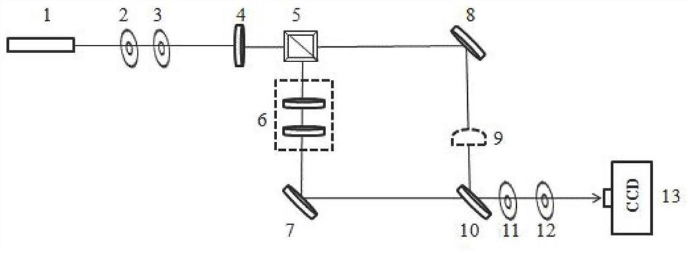
[0068] When the laser light source 1 is a scalar beam, the laser is reflected and transmitted by the first half-wave plate 4 and the polarizing beam splitter 5, and serves as signal light and reference light respectively. After the signal light is reflected to the output mirror 10 by the first total reflection mirror 7, optical heterodyne interference occurs between the reference light and the reference light reflected to the output mirror 10 by the second total reflection mirror 8. At this time, as Image 6 As shown on the left, the CCD image sensor 13 detects its interference signal, and its scalar light beam does not interfere, and is still in a circular spot state;
[0069] When the wave plate group 6 is set between the polarizing beam splitter 5 and the first total reflection mirror 7, the wave plate group 6 can be a second half-wave plate, the signal light rotates the polarization direction through the second half-wave plate, and the polarization direction occurs 90° rot...
Embodiment 2
[0071] When the laser light source 1 is a phase vortex beam, the reference light transmitted from the polarization beam splitter 5 is blocked first, and the signal light reflected from the polarization beam splitter 5 passes through the wave plate group 6, and the wave plate group 6 is a first Two half-wave plates; the signal light rotates the polarization direction through the second half-wave plate, and the polarization direction is rotated by 90°. After the signal light passes through the polarization beam splitter 5, its polarization direction is consistent with the transmission polarization direction of the polarization beam splitter 5, that is, the signal The polarization direction of the light is consistent with that of the reference light;
[0072] When the reference light is not blocked, the signal light and the reference light are reflected and transmitted by the output mirror 10 to generate optical heterodyne interference, and the CCD image sensor 13 observes that th...
Embodiment 3
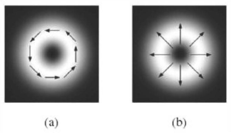
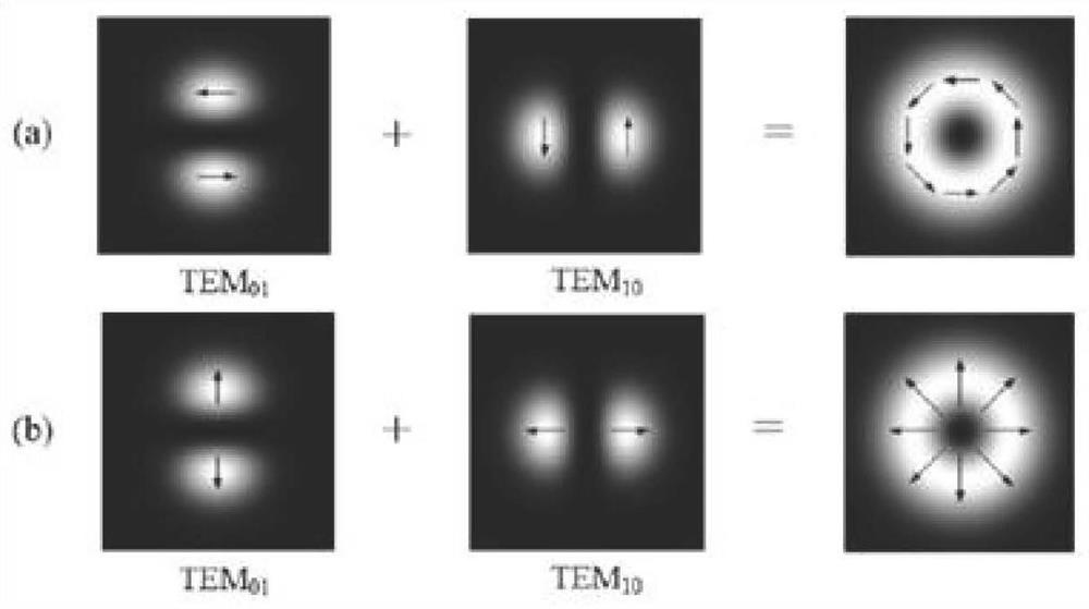
[0077] When the laser light source 1 is a vector beam (without a helical phase), the laser reflected and transmitted by the first half-wave plate 4 and the polarizing beam splitter 5 are respectively used as signal light and reference light, and the radially polarized light can be decomposed into two beams Linearly polarized light in which both the electric field intensity distribution and the direction of the electric field are orthogonal to each other. On the contrary, two linearly polarized TEM01 modes whose intensity and polarization are orthogonal to each other and have the same phase are superimposed on each other to obtain radially polarized light.
[0078] When the wave plate group 6 is not placed between the polarizing beam splitter 5 and the first total reflection mirror 7, a beam expander 9 is placed between the second total reflection mirror 8 and the output mirror 10, and the signal light is reflected to the output mirror by the total reflection mirror 10. The ref...
PUM
 Abstract
Description
Claims
Application Information
 - R&D
- Intellectual Property
- Life Sciences
- Materials
- Tech Scout
- Unparalleled Data Quality
- Higher Quality Content
- 60% Fewer Hallucinations
Browse by: Latest US Patents, China's latest patents, Technical Efficacy Thesaurus, Application Domain, Technology Topic, Popular Technical Reports.
© 2025 PatSnap. All rights reserved.Legal|Privacy policy|Modern Slavery Act Transparency Statement|Sitemap|About US| Contact US: help@patsnap.com


