Nitrogen foam induced flow experimental device for simulating coiled tubing and use method thereof

A technology of nitrogen foam and experimental equipment, which is applied in the direction of earthwork drilling, production fluid, measurement, etc., can solve the problems of inability to monitor pressure changes, inability to realize automatic addition of reactants, inability to simulate reservoir pressure, etc.

Pending Publication Date: 2021-09-07
CNOOC ENERGY TECH & SERVICES
View PDF6 Cites 0 Cited by
  • Summary
  • Abstract
  • Description
  • Claims
  • Application Information

AI Technical Summary

Problems solved by technology

[0004] The present invention overcomes the deficiencies in the prior art. The bubble discharge device cannot monitor pressure changes, cannot realize the mixing of nitrogen and foaming agent system, cannot realize the automatic addition of reactants, cannot realize the control of gas-liquid ratio, and cannot simulate oil In order to solve the problem of hidden pressure and the bubble discharge device is not pressure-resistant, a nitrogen foam induction spraying experimental device simulating coiled tubing and its use method are provided. The invention can monitor the pressure change during the reaction process and realize the nitrogen and foaming process The mixing of the agent system under high temperature and high pressure conditions realizes the automatic addition of reactants, the combination of pressure gauge and valve opening adjustment is used to realize the constant gas-liquid ratio and reservoir pressure, and the thread sealing method is used to improve the sealing performance of the device

Method used


Image

  • Nitrogen foam induced flow experimental device for simulating coiled tubing and use method thereof

Examples


Embodiment 1

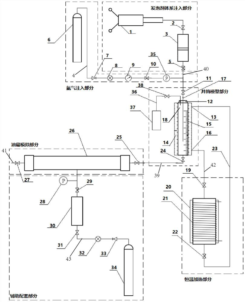
[0037] A nitrogen foam induced blowout experiment device for simulating coiled tubing, including a nitrogen injection part, a foaming agent system injection part, a wellbore model part, a constant temperature heating part, a reservoir simulation part and auxiliary supporting parts,

[0038] The nitrogen injection part comprises a nitrogen cylinder 6, a pressure reducing valve 7, a pressure regulating valve 8 and a nitrogen valve 10. The outlet of the nitrogen cylinder 6 is connected to the foaming nitrogen mixing valve 11 through the first pipeline 4, and on the first pipeline 4 is Set the pressure reducing valve 7, the pressure regulating valve 8 and the nitrogen valve 10 sequentially from left to right;

[0039] The foaming agent system injection part includes a metering pump 1, a foaming inlet valve 2, a piston container 3 and a foaming outlet valve 5, the outlet of the metering pump 1 is connected to the inlet of the foaming inlet valve 2, and the outlet of the foaming inle...

Embodiment 2

[0044] On the basis of Embodiment 1, the constant temperature heating part includes a water bath inlet pipeline 42, a water bath drain pipeline 23, a water bath device 20 and a heating wire 21, and the heating wire 21 is wound outside the water bath device 20, and the first part of the water bath inlet pipeline 42 The end is connected to the constant temperature water inlet 16 arranged on the constant temperature water bath device 14, the tail end of the water bath inlet pipe 42 is connected to the top of the water bath device 20, and a heating outlet valve 19 is arranged on the water bath inlet pipe 42, and the water bath drainage pipe The head end of 23 links to each other with the constant temperature water outlet 13 that is arranged on the constant temperature water bath device 14, and the tail end of water bath drainage pipeline 23 links to each other with the bottom end of water bath device 20, is provided with heating inlet valve 22 on water bath drainage pipeline 13.

Embodiment 3

[0046] On the basis of the second embodiment, a flow meter 9 is also provided on the first pipeline 4 between the pressure regulating valve 8 and the nitrogen valve 10 .

[0047] A second pressure gauge 35 is also provided on the first pipeline 4 between the nitrogen valve 10 and the foaming nitrogen mixing valve 11 .

[0048] The high-pressure visible wellbore 18 adopts the structure of pressure-resistant and temperature-resistant tempered glass. The pressure-resistant pressure of the high-pressure visible wellbore 18 is 4-5MPa, and the temperature-resistant temperature of the high-pressure visible wellbore 18 is 160-180°C. A scale scale 15 is provided on the side wall of the casing, which is used to adjust the insertion height of the coiled tubing 17 in real time, so as to realize the research on the influence of the position of the coiled tubing 17 on the process effect.

[0049] A first pressure gauge 28 is also provided on the pressure simulation pipeline 73 between the p...


PUM


Abstract

The invention provides a nitrogen foam induced flow experimental device for simulating coiled tubing and a use method thereof. The nitrogen foam induced flow experimental device comprises a nitrogen injection part, a foaming agent system injection part, a shaft model part, a constant-temperature heating part, an oil reservoir simulating part and an auxiliary matching part, wherein both the nitrogen injection part and the foaming agent system injection part are connected with the shaft model part, the constant-temperature heating part is used for providing constant experimental temperature for the shaft model part, the shaft model part is connected with the oil reservoir simulating part, the shaft model part is used for monitoring fluid return displacement in real time, and the oil reservoir simulating part is used for simulating the oil reservoir blocking capacity. According to the nitrogen foam induced flow experimental device, the pressure change in the reaction process can be monitored, the mixing of nitrogen and a foaming agent system under the high-temperature and high-pressure conditions in the reaction process is achieved, the automatic adding of reactants is achieved, the constant gas-liquid ratio and oil reservoir pressure is achieved through combination of a pressure gauge and valve opening adjustment, and the sealing performance of the device is improved in a threaded sealing mode.

Description

technical field [0001] The invention relates to the technical field of petroleum exploitation, and more specifically relates to a nitrogen foam induced injection experimental device for simulating a coiled tubing and a method for using the same. Background technique [0002] At present, the coiled tubing gas lift induction technology is mainly used to induce blowout in oil wells, but for the oil wells with insufficient formation pressure and severe blockage of condensate oil, the implementation effect of the coiled tubing gas lift induction technology is not good, the construction cost is high, time-consuming and laborious, and even Can't lure and spray successfully, cause serious waste of resources. Aiming at the limitations of the coiled tubing gas lift induced injection process, combined with the advantages of foam drainage, a combined process technology of coiled tubing gas lift induced injection process and foam drainage gas recovery technology is proposed, namely the c...

Claims


Application Information

Patent Timeline
Patent Type & Authority Applications(China)
IPC IPC(8): E21B43/16E21B43/22E21B47/06
CPCE21B43/166E21B47/06
Inventor 郑继龙祖健张洪赵军陈平张润芳马认琦蒋军王成胜蒲家良刘敏黄波胡雪叶春波左清泉
Owner CNOOC ENERGY TECH & SERVICES
Why Eureka
Try Eureka