
Target accurate positioning method in pulse laser ranging and application thereof

A technology of pulse laser ranging and positioning method, which is applied in the directions of measuring distance, measuring device, line-of-sight measurement, etc. It can solve the problems of large determination error of waveform peak point position, distortion of target echo signal waveform, and low accuracy of ranging and positioning. , to achieve the effect of accurate acquisition, keeping the waveform characteristics unchanged, and improving the detection signal-to-noise ratio

Active Publication Date: 2021-09-07
ZHENGZHOU UNIVERSITY OF AERONAUTICS +2
View PDF8 Cites 0 Cited by
  • Summary
  • Abstract
  • Description
  • Claims
  • Application Information

AI Technical Summary

Problems solved by technology

[0005] In the prior art, the signal-to-noise ratio gain is not large after the echo signal is filtered, and the target echo signal waveform after filtering is distorted, resulting in a large error in determining the position of the peak point of the waveform, and the positioning accuracy of the distance measurement is not high

Method used


Image

  • Target accurate positioning method in pulse laser ranging and application thereof
  • Target accurate positioning method in pulse laser ranging and application thereof
  • Target accurate positioning method in pulse laser ranging and application thereof

Examples


Embodiment approach

[0056] According to the technical solution of the present invention, some specific implementation methods include:

[0057] (1) Decompose and reconstruct the laser echo signal by EMD method to achieve signal noise reduction

[0058] It can further include:

[0059] Based on the EMD method, the laser echo signal is adaptively decomposed, and the adaptive decomposition includes: decomposing the signal into several Intrinsic Mode Functions (Intrinsic Mode Function, IMF) and residual items according to the amplitude-frequency characteristics of the signal by the EMD method , where IMF is a zero-point symmetric function defined by local maxima and minima, with an equal number of extreme points and envelope zero-crossing points; the residual term is a constant or a monotonic function or a single extreme point function;

[0060] More specifically, if the digitally sampled echo signal f(k) in the pulsed laser target gate of the airborne platform is a sequence containing noise, as fol...

Embodiment 1

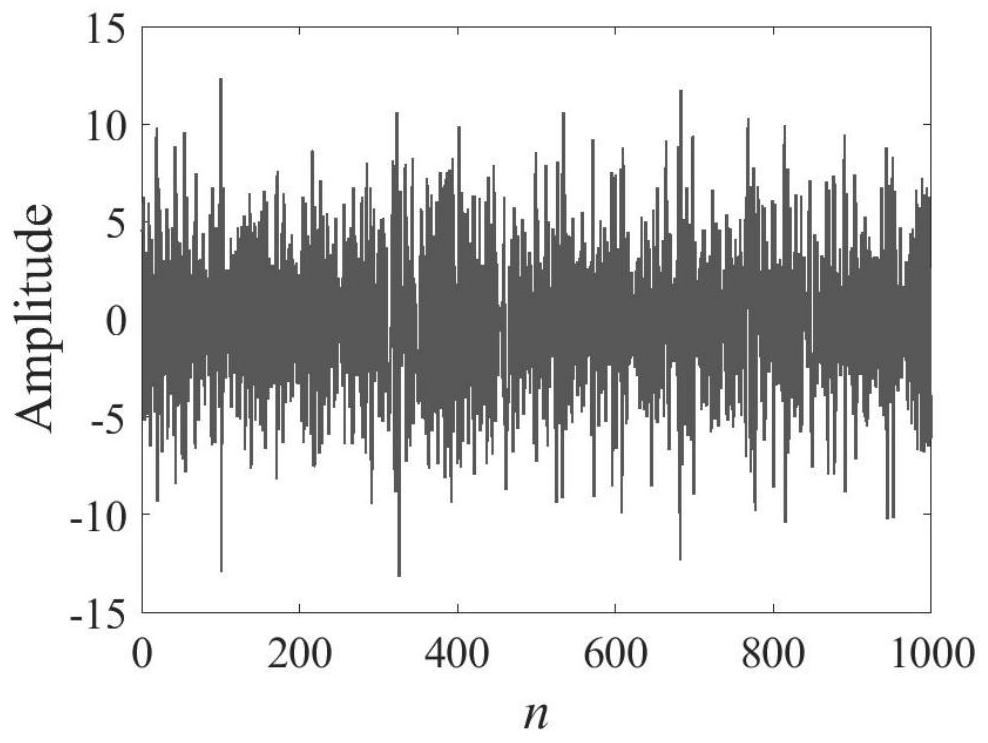
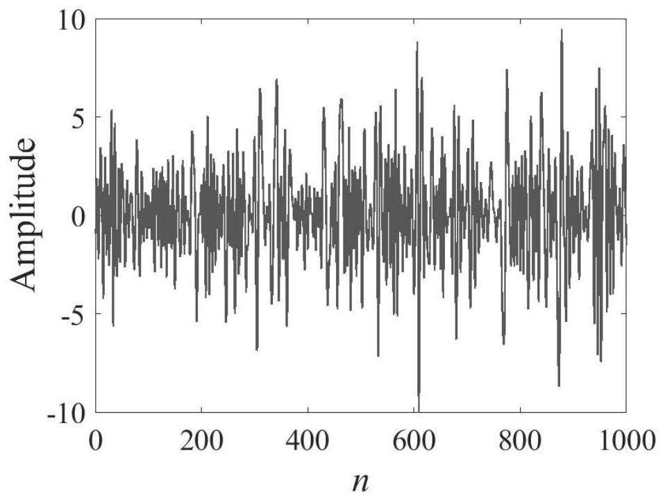
[0099] According to the above specific implementation, the ideal echo signal is first constructed on the Matlab software platform, and Gaussian white noise is added to the echo signal, and the noisy echo signal is used as the processing object, and the proposed denoising method is used for denoising processing.

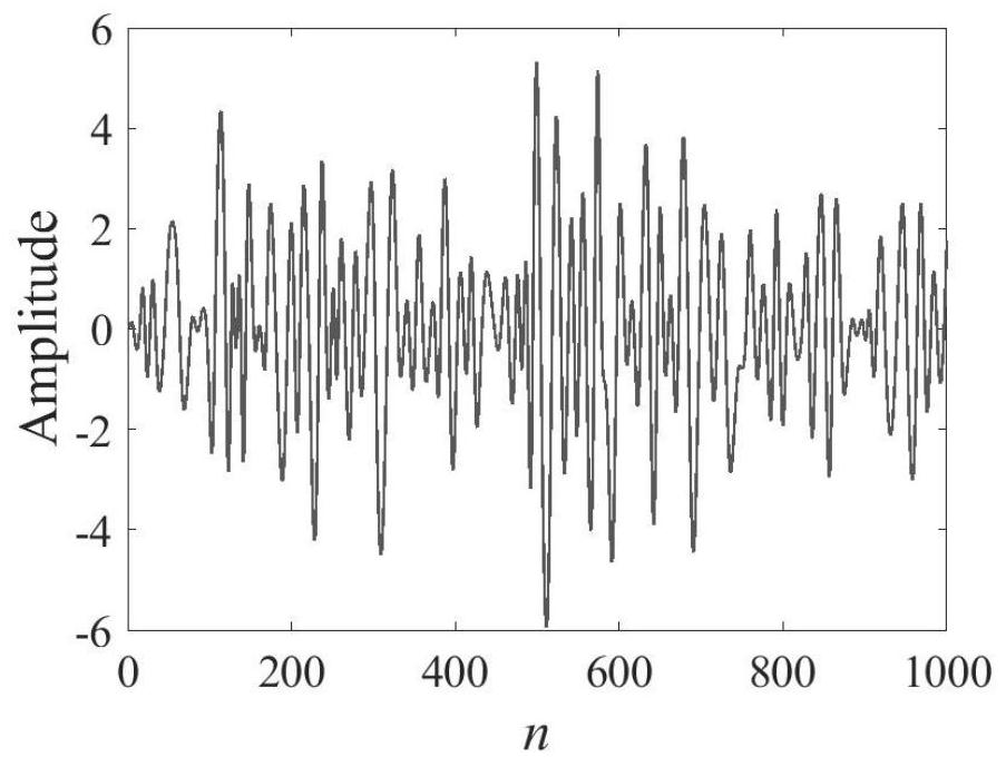
[0100] The EMD decomposition of the echo signal under the above conditions can be obtained as follows: Figure 1-9 The decomposition diagrams of each IMF item and residual item are shown, with Figure 1-8 Respectively represent the first IMF item, the second IMF item, the third IMF item, ..., the eighth IMF item of the echo signal. attached Figure 9 represents the final residual term.

[0101] The comparison of the target echo signal sequence obtained through the EMD decomposition of the present invention, the target echo signal waveform after Gaussian fitting and the ideal pulse laser target echo signal is attached Figure 10 As shown, it can be seen that the met...


PUM


Abstract

The invention discloses a target accurate positioning method in pulse laser ranging and application thereof. The positioning method comprises the steps of performing EMD decomposition on an echo signal, obtaining a denoised echo signal sequence according to selection of a decomposed intrinsic mode function item and a final residual item, extracting a target signal sequence from the denoised echo signal sequence, obtaining a peak value point of the target signal sequence through maximum value point search, and performing waveform curve fitting on the target signal sequence, and performing correction according to an obtained peak point to obtain a target signal waveform. The method can accurately obtain the target position, and is especially suitable for being applied to an airborne pulse laser range finder.

Description

technical field [0001] The invention relates to the technical field of pulse laser target detection of photoelectric radar. Background technique [0002] Modern aircraft are equipped with an airborne photoelectric detection system for detecting targets in the air, on the ground, and on the sea. It is mainly composed of a visible light imaging (also known as television) unit, an infrared thermal imaging unit, and a laser ranging unit. Among them, the visible light imaging (television) unit is used to image the natural light reflected by the target, and the infrared unit is used to passively detect and image the thermal radiation of the target through the mid-infrared band, search and detect the target's azimuth, such as azimuth, elevation angle, and laser ranging The unit emits pulsed laser beams in the near-infrared band to irradiate the aiming target to obtain the radial distance of the target, so as to realize the positioning of the aircraft target in three-dimensional spa...

Claims


Application Information

Patent Timeline
Patent Type & Authority Applications(China)
IPC IPC(8): G01S17/48
CPCG01S17/48Y02A90/10
Inventor 马鹏阁陶然孙俊灵单涛郝培育李伟张鹏韩红印刘兆瑜胡磊力羊毅金秋春
Owner ZHENGZHOU UNIVERSITY OF AERONAUTICS
Learn More