
Low-shear tackifying leakage-proof early-strength paste system

A low-shear, cement slurry technology, applied in the direction of drilling compositions, chemical instruments and methods, reagents, etc., can solve the problems of poor application effect of fiber materials, affecting the uniformity of cement slurry, and difficult pumping of cement slurry, etc.

Active Publication Date: 2021-09-10
CHINA UNIV OF PETROLEUM (EAST CHINA)
View PDF3 Cites 0 Cited by
  • Summary
  • Abstract
  • Description
  • Claims
  • Application Information

AI Technical Summary

Problems solved by technology

The effect of fiber materials alone is poor, and the effective content is difficult to guarantee, and the fibers are easy to form balls during the cement slurry pumping process, which affects the uniformity of the cement slurry; while the long-term mechanical properties of low-density cement slurry are difficult to guarantee, and the leakage of the high-permeability layer The capacity is weaker than the crack leakage capacity, so it is not necessary to use fibers for leakage prevention
Based on Darcy's law, for high-permeability reservoirs, increasing the viscosity of cement slurry can also effectively prevent leakage, but increasing the viscosity of cement slurry will make it difficult to pump the cement slurry and affect the displacement efficiency.

Method used


Image

  • Low-shear tackifying leakage-proof early-strength paste system
  • Low-shear tackifying leakage-proof early-strength paste system
  • Low-shear tackifying leakage-proof early-strength paste system

Examples


Embodiment 1

[0026] Example 1 A low-shear thickening type leak-proof early-strength cement slurry system

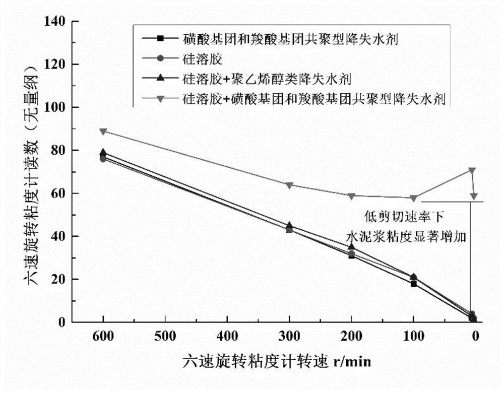
[0027] 100 parts of G grade oil well cement + 2.5 parts of sulfonic acid group and carboxylic acid group copolymerized fluid loss reducer + 0.5 parts of sulfonated aldehyde and ketone condensation polymer type dispersant + 5 parts of silica sol (SiO 2 The content is 40%, and the density of silica sol is 1.3g / cm 3 , nano silicon dioxide particle size 5~15nm)+water, the total mass of water: solid phase total mass=0.44. The cement slurry system is denoted as C1

Embodiment 2

[0028] Example 2 A low-shear thickening type leak-proof early-strength cement slurry system

[0029] 100 parts of G grade oil well cement + 4 parts of sulfonic acid group and carboxylic acid group copolymerized fluid loss reducer + 0.5 part of sulfonated aldehyde and ketone condensation polymer type dispersant + 6 parts of silica sol (SiO 2 The content is 35%, and the density of silica sol is 1.3g / cm 3 , nano silicon dioxide particle size 5~15nm)+water, the total mass of water: solid phase total mass=0.44. The cement slurry system is recorded as C2

Embodiment 3

[0030] Embodiment 3 comparative samples—only add silica sol

[0031] 100 parts of G grade oil well cement + 0.5 parts of sulfonated aldehyde and ketone polycondensate type dispersant + 6 parts of silica sol (SiO2 content 40%, silica sol density 1.3g / cm 3 , nano silicon dioxide particle size 5~15nm)+water, the total mass of water: solid phase total mass=0.44. The cement slurry system is recorded as C3


PUM

PropertyMeasurementUnit
Densityaaaaaaaaaa
Particle sizeaaaaaaaaaa

Abstract

The invention relates to the field of oilfield chemistry and oil and gas well cementing materials, in particular to a low-shear tackifying leakage-proof early-strength cement paste system. The cement paste system comprises oil well cement and comprises the following raw materials in parts by weight: 100 parts of G-grade oil well cement, 2.0-5.0 parts of a fluid loss agent, 0.25-1.5 parts of a dispersing agent, 4-8 parts of silica sol and 40-55 parts of water. According to the invention, the silica sol and the oil well cement fluid loss agent containing a carboxylic acid group are combined and utilized, so the composition of cement paste is simplified, and the cement paste has early strength performance; the cement paste has the characteristics of low viscosity under the action of high shear force and dramatic viscosity increase under the action of low shear force, so the rheological property of the cement paste is excellent in the process of pumping the cement paste, and after displacement is in place, the cement paste is rapidly subjected to viscosity improvement in a shaft so as to prevent leakage; and the cement paste system has important significance for improving the well cementation quality of a shallow weak cementation reservoir.

Description

technical field [0001] The invention relates to the fields of oilfield chemistry and oil-gas well cementing materials, in particular to a low-shear viscosity-increasing type leak-proof early-strength cement slurry system. Background technique [0002] For shallow weakly cemented reservoirs (commonly found in the sea, such as the South my country Sea and Bohai Bay in China), during cementing, due to the weak cementation of the reservoir, it has the characteristics of high permeability, and the cement slurry can easily penetrate into the reservoir under the action of pressure difference, resulting in The leakage of cement slurry affects the design return height of cement slurry and the cementing quality. At the same time, the leakage of cement slurry into the deep formation will significantly reduce the permeability of the reservoir and affect the production efficiency. Well waiting time increases the cost of well construction. [0003] The common way of preventing leakage of c...

Claims


Application Information

Patent Timeline
IPC IPC(8): C09K8/487
CPCC09K8/487Y02P20/141
Inventor 田辉步玉环柳华杰郭胜来郭辛阳曹成章
Owner CHINA UNIV OF PETROLEUM (EAST CHINA)
Learn More