SF6 gas filling device

An inflatable device, gas technology, applied in the direction of gas/liquid distribution and storage, container filling methods, fixed capacity gas storage tanks, etc., can solve the problems of inconspicuous, falling, not fast, etc.

Active Publication Date: 2021-09-10
国网安徽省电力有限公司亳州供电公司 +1
View PDF10 Cites 0 Cited by
  • Summary
  • Abstract
  • Description
  • Claims
  • Application Information

AI Technical Summary

Problems solved by technology

However, when replenishing gas, the SF6 stored in the steel cylinder is in a liquid state inside the cylinder. When it is inflated, the volume of SF6 expands rapidly when the liquid state is transformed into a gas, and accompanied by a large amount of heat absorption, the surrounding water vapor condenses into frost and adheres to the bottle. Body and pressure reducing valve and other parts, the temperature inside the steel cylinder also drops sharply, the output pressure of the steel cylinder is getting lower and lower, and the pressure in the equipment increases with the increase of the filling amount, so that the gas filling speed of the steel cylinder is slow, and the pressure balance is quickly reached. When the inflation stops, the gas in the equipment often does not reach the rated pressure value. At this time, there is still a large amount of sulfur hexafluoride in the steel cylinder, which cannot be charged any more, and the inflation efficiency is reduced.
[0003] In addition, due to condensation on steel cylinders and pipelines, the temperature in the steel cylinders drops, and even the form solidifies. Due to its large flow velocity and pressure, sulfur hexafluoride after decompression often enters in the form of both liquid and gaseous states. Equipment, during the inflation process, we can only judge the inflation volume based on the pressure gauge data with temperature detection, and cannot accurately estimate the actual value of sulfur hexafluoride, and the deviation is large
After the gas enters the equipment and stabilizes for a long time, the liquid sulfur hexafluoride is completely vaporized, and the gas pressure in the equipment increases, even exceeding its safe p

Method used


Image

  • SF6 gas filling device
  • SF6 gas filling device
  • SF6 gas filling device

Examples


Embodiment Construction

[0027] The present invention will be described in further detail below in conjunction with the accompanying drawings and embodiments.

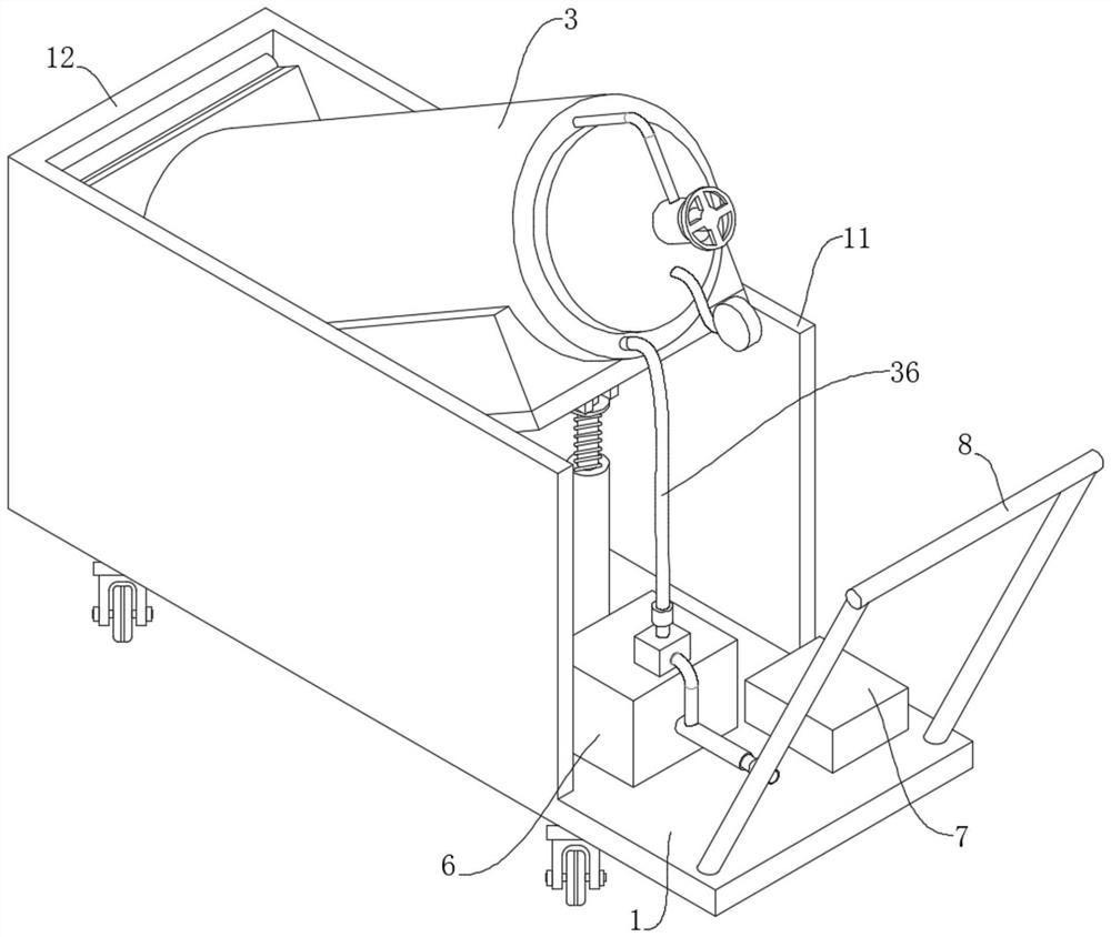
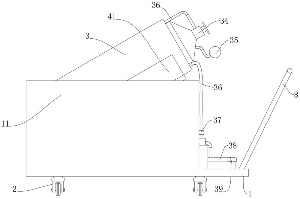
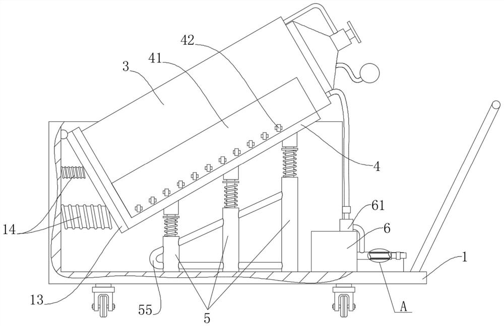
[0028] see Figure 1 to Figure 6 .

[0029] A kind of SF6 gas inflating device of the present invention comprises base 1, a plurality of castors 2 arranged under said base 1 and an inflatable bottle 3 arranged on said base 1, said inflatable bottle 3 includes a tank for storing SF6 gas The inner bottle body 31 and the outer bottle body 32 arranged outside the outer peripheral surface of the inner bottle body 31, there is a gap between the inner bottle body 31 and the outer bottle body 32, and the second bottle body is evenly distributed in the gap. A heating wire 33 is filled with heat conduction oil or water or other heat transfer medium, preferably, because of the large specific heat capacity of water, low price, and because the temperature of water will not rise to make the water boil when heated, so water is selected as a heat transfer m...


PUM


Abstract

The invention provides an SF6 gas filling device which comprises a base, trundles and a gas filling bottle. The gas filling bottle comprises an inner bottle body and an outer bottle body, a first heating wire is arranged between the inner bottle body and the outer bottle body, a heat transfer medium is filled between the inner bottle body and the outer bottle body, and the inner bottle body is provided with a gas valve, a resistance teletransmission pressure gauge and a gas conveying pipe connected with the gas valve; and a first thermistor, a heating sleeve and a second thermistor are sequentially installed on the gas conveying pipe, a second heating wire is arranged in the heating sleeve, the first thermistor, the resistance teletransmission pressure gauge and the first heating wire are connected into a circuit in series, and the second thermistor and the second heating wire are connected into a circuit in series. The bottle bodies can be rapidly and effectively heated, so that the bottle bodies are uniformly heated, the heat absorption effect of the bottle bodies is improved, rapid inflation is realized, the gas filling efficiency is improved, and the temperature of gas flowing out of the gas conveying pipe can be maintained in a fixed range.

Description

technical field [0001] The invention relates to the technical field of inflators, in particular to an SF6 gas inflator. Background technique [0002] In recent years, with the rapid development of my country's electric power industry and the improvement of technical equipment, a large number of SF6 electrical equipment has been put into operation. SF6 (sulfur hexafluoride) gas is widely used in power systems due to its excellent insulation and arc extinguishing properties. It has almost become the only insulation and arc-extinguishing medium used in medium-voltage, high-voltage and ultra-high-voltage switches. Due to the large number of SF6 equipment and long-term operation, there is often the possibility of air leakage, which requires regular air replenishment. However, when replenishing gas, the SF6 stored in the steel cylinder is in a liquid state inside the cylinder. When it is inflated, the volume of SF6 expands rapidly when the liquid state is transformed into a gas, an...

Claims


Application Information

Patent Timeline
IPC IPC(8): F17C7/02F17C13/10F17C13/02F16F15/067
CPCF17C7/02F17C13/10F17C13/025F16F15/067
Inventor 国伟辉王高洁荆林远张钊瑞孟晗张奥谭勇孔伟杰樊承鹏李强
Owner 国网安徽省电力有限公司亳州供电公司
Why Eureka
Try Eureka