Eureka AIR delivers breakthrough ideas for toughest innovation challenges, trusted by R&D personnel around the world.

Multifunctional VHP sterilizer

A sterilizer and multi-functional technology, applied in household heating, space heating and ventilation details, heating methods, etc., can solve problems such as high use conditions, long disinfection cycle, and poor HEPA penetration

Pending Publication Date: 2021-09-10
中科圣杰(深圳)科技集团有限公司
View PDF0 Cites 0 Cited by
  • Summary
  • Abstract
  • Description
  • Claims
  • Application Information

AI Technical Summary

Problems solved by technology

[0003] However, most of the currently used sterilizers require high conditions of use, and the disinfection cycle is long. The gas generated by the operation will cause great damage to the human body, equipment and the surrounding environment. At the same time, the penetration of HEPA Poor, high initial investment cost of equipment, etc.

Method used


Image

  • Multifunctional VHP sterilizer
  • Multifunctional VHP sterilizer
  • Multifunctional VHP sterilizer

Examples


no. 1 example

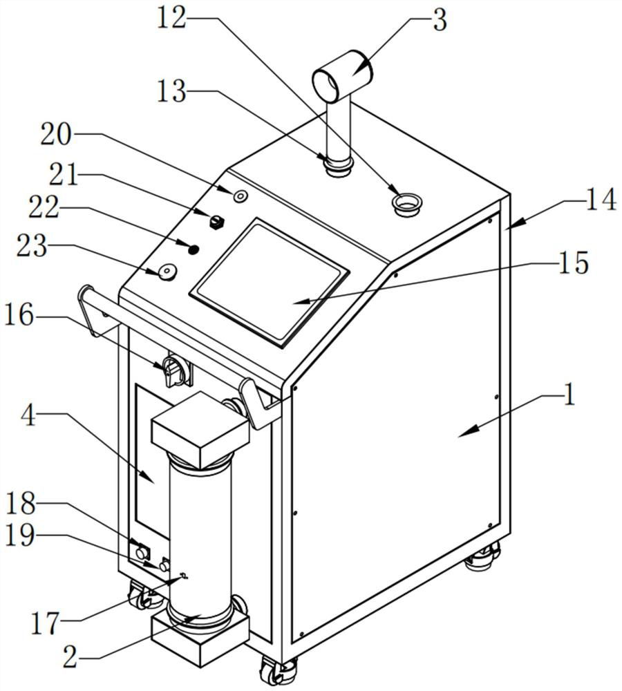
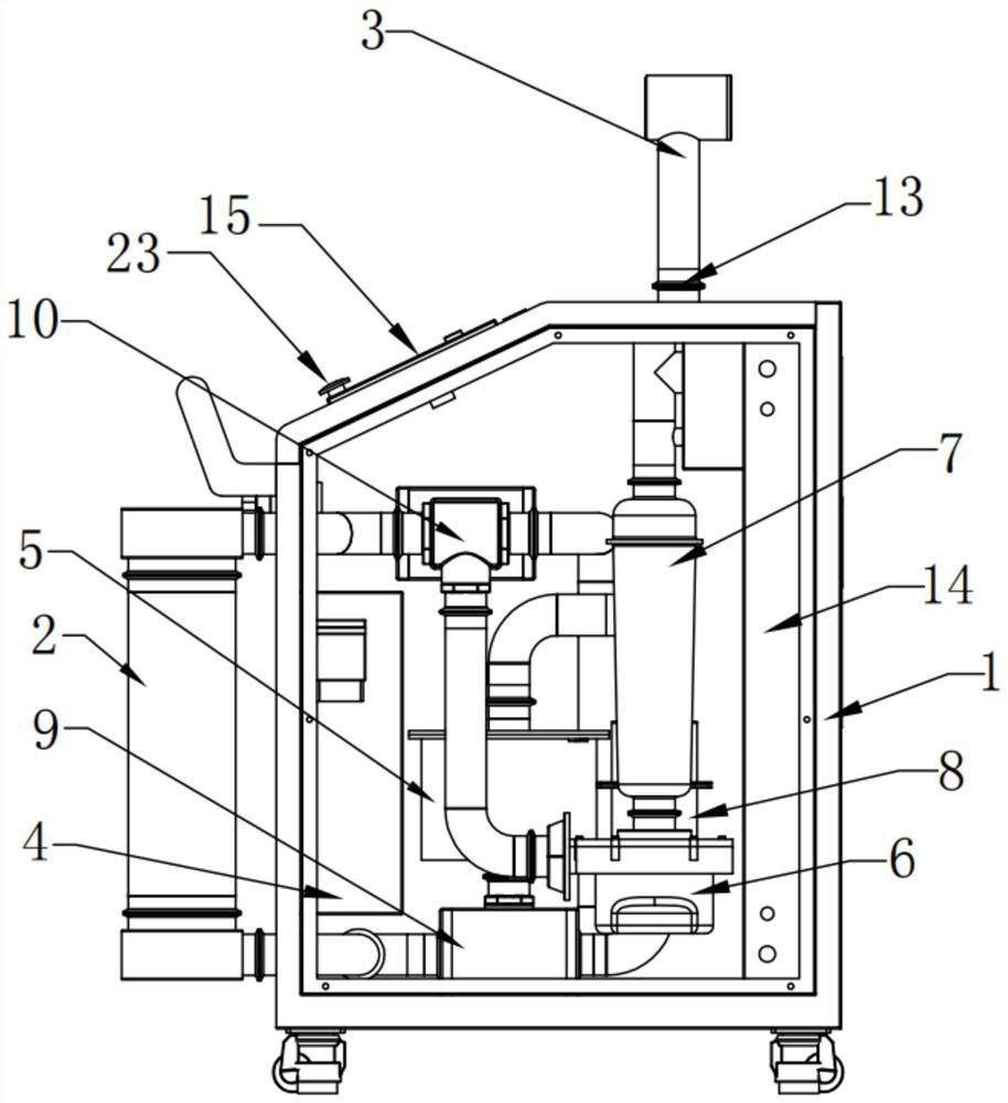
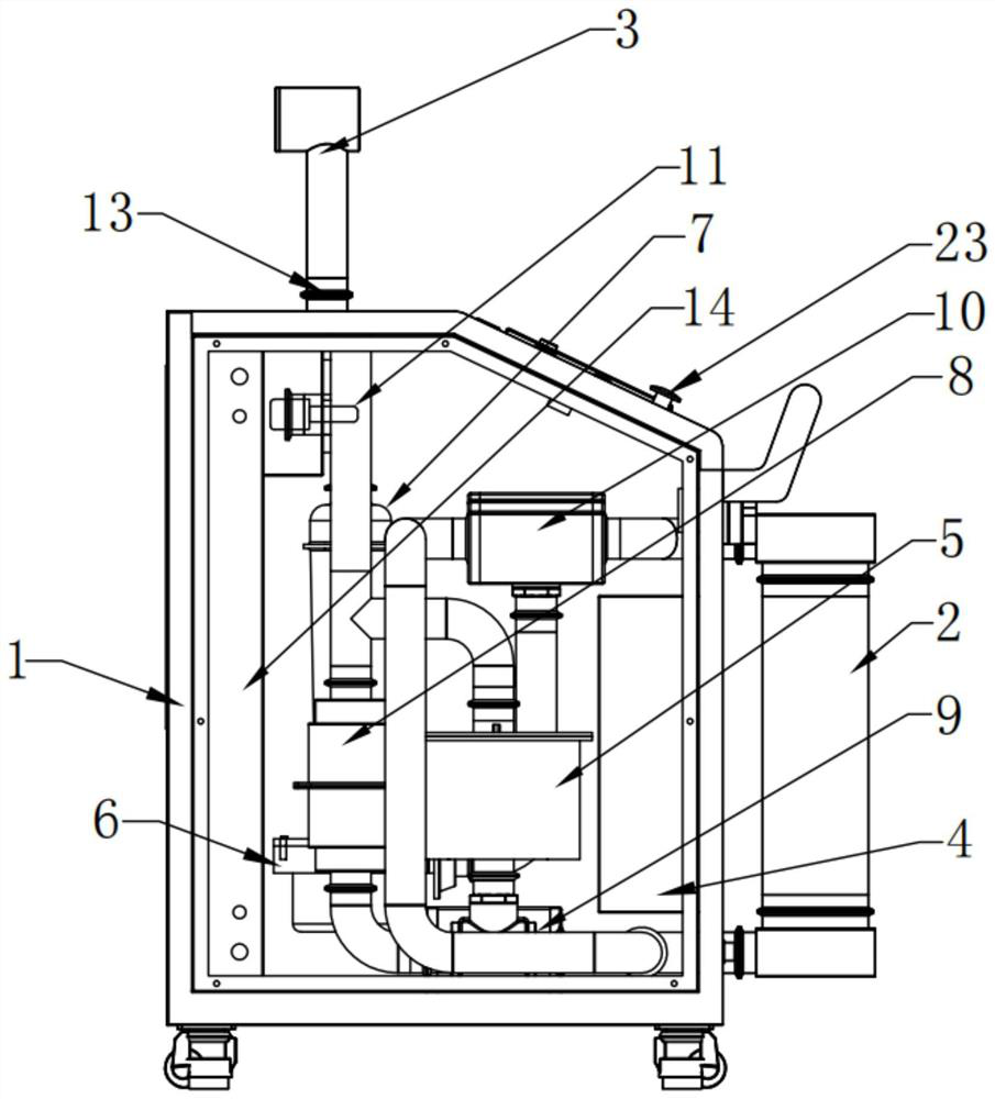
[0029] Please refer to Figure 1-4 . The multifunctional VHP sterilizer includes: a body 1, an external drying system 2 and a hydrogen peroxide solution cabinet 4 are arranged on one side of the body 1, a Venturi nozzle 3 is arranged on the top of the body 1, and the body 1 A VHP flash evaporator 5, a speed-regulating blower 6, a filter 7 and a degrader 8 are arranged inside, and the VHP flash evaporator 5, a speed-regulating blower 6, a filter 7 and a degrader 8 are all connected with the external drying system 2 and The hydrogen peroxide solution cabinet 4 is communicated through a parallel pipeline, the degrader 8 is communicated with the Venturi nozzle 3, and the parallel pipeline is provided with a first electric ball valve 9, a second electric ball valve 10 and a three-way valve. A concentration probe 11, the first electric ball valve 9 is located below the VHP flash evaporator 5, the second electric ball valve 10 is located above the VHP flash evaporator 5, and the thr...

no. 2 example

[0044] Based on the multifunctional VHP sterilizer provided in the first embodiment of the present application, the second embodiment of the present application proposes another multifunctional VHP sterilizer. The second embodiment is only a preferred mode of the first embodiment, and the implementation of the second embodiment will not affect the independent implementation of the first embodiment.

[0045] The second embodiment of the present invention will be further described below in conjunction with the drawings and implementation methods.

[0046] Please refer to Figure 5-7 , the multifunctional VHP sterilizer further includes a screen protection mechanism, the screen protection mechanism is arranged on the body 1 , and the screen protection mechanism corresponds to the main operation screen 15 .

[0047] The screen protection mechanism includes a mounting piece 24, a supporting piece 25, a flip cover 26, an inner sealing plate 27, a fixing mechanism and an emergency t...


PUM


Abstract

The invention provides a multifunctional VHP sterilizer. The multifunctional VHP sterilizer comprises a machine body, an external drying system and a hydrogen peroxide solution cabinet are arranged on one side of the machine body, a Venturi nozzle is arranged at the top of the machine body, a VHP flash evaporator, a speed regulation air blower, a filter and a degradation device are arranged in the machine body, the VHP flash evaporator, the speed regulation air blower, the filter and the degradation device are all communicated with the external drying system and the hydrogen peroxide solution cabinet through parallel pipelines, the degradation device is communicated with the Venturi nozzle, and a first electric ball valve, a second electric ball valve and a three-in-one concentration probe are arranged on the parallel pipelines. The multifunctional VHP sterilizer provided by the invention has the advantages that the multifunctional VHP sterilizer can be used at room temperature, the sterilization period is short, the damage to a human body, equipment and the surrounding environment is reduced after operation, the penetrability to HEPA is relatively high, and the initial investment cost of the equipment is relatively low.

Description

technical field [0001] The invention relates to the technical field of sterilization equipment, in particular to a multifunctional VHP sterilizer. Background technique [0002] With the rapid development of society, the level of science and technology continues to improve, and people's requirements for the living environment are getting higher and higher. Now the social industry is developed, resulting in a decline in air quality. Many occasions such as factories, laboratories, shopping malls or homes need to be cleaned. The air is purified to eliminate harmful bacteria in the air, so that human health is guaranteed. [0003] However, most of the currently used sterilizers require high conditions of use, and the disinfection cycle is long. The gas generated by the operation will cause great damage to the human body, equipment and the surrounding environment. At the same time, the penetration of HEPA Poor, high initial investment cost of equipment and other issues. [0004]...

Claims


Application Information

Patent Timeline
IPC IPC(8): F24F8/80F24F8/24F24F8/108F24F13/32F24F11/89F24F11/64F24F11/61F24F11/52F24F11/526F24F13/28
CPCF24F8/80F24F8/24F24F8/108F24F13/32F24F11/89F24F11/64F24F11/61F24F11/52F24F11/526F24F13/28Y02A50/20
Inventor 田金丰
Owner 中科圣杰(深圳)科技集团有限公司
Why Eureka
Eureka Blog
Learn More