Protection method for wet uncapping of plastic package device
A device and wet technology, which is used in the protection field of wet cap opening of plastic encapsulated devices, can solve the problems of inaccurate cap opening area and damaged device function.
- Summary
- Abstract
- Description
- Claims
- Application Information
AI Technical Summary
Problems solved by technology
Method used
Image

Examples
Embodiment 1
[0037] A protection method for wet uncapping of plastic-encapsulated devices, comprising the steps of:
[0038] Step 1) Obtain the size of the plastic-encapsulated device, and design a bracket based on the size of the plastic-encapsulated device;
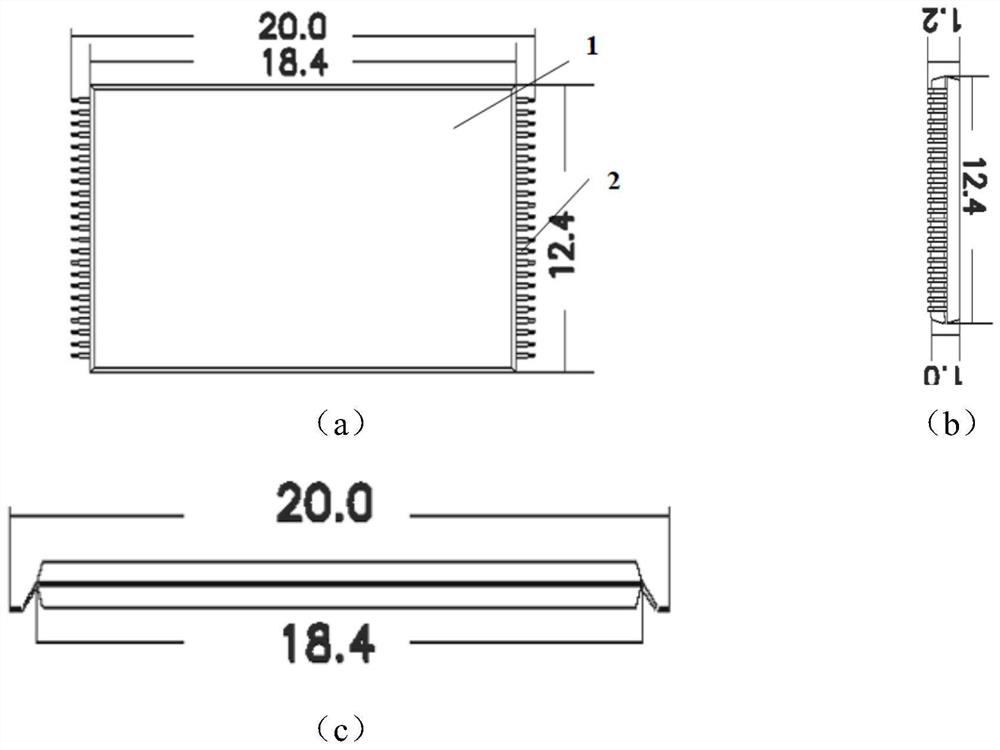
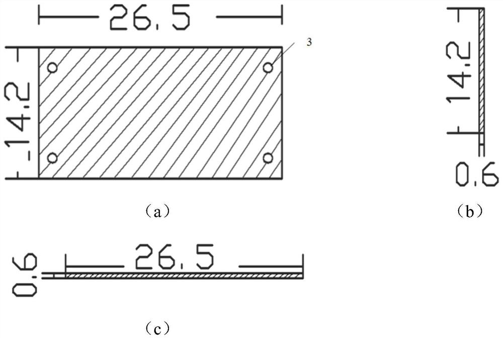
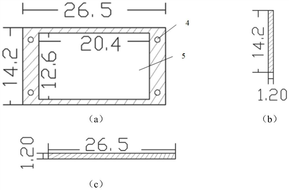
[0039] The plastic-encapsulated device includes a device body 1 and lead legs 2 drawn from both sides of the device body, and the structural dimensions are as follows: figure 1 As shown; the bracket includes a base 11 and a frame 12 installed on the base 11, the center of the frame 12 is provided with a through groove 5 for inlaying and fixing the device body, and the structural dimensions are as follows figure 2 and image 3 shown;
[0040] Step 2) installing the device body 1 in the through groove 5;
[0041] Step 3) Ultrasonic scanning is performed on the plastic-encapsulated device to be uncapped to obtain the uncapped area 8 and the non-capped area;
[0042] Step 4) Wrap a layer of acid and alkali-resistant tape around the...
Embodiment 2
[0044] Except for the following content, all the other contents are the same as in Example 1.
[0045] like Figure 4 As shown, the side of the frame 12 is provided with a first positioning hole 3, and the side of the base 11 is provided with a second positioning hole 4 at a position corresponding to the first positioning hole 3, the first positioning hole 3 and the second positioning hole 4 The base 11 and the frame 12 are aligned and fixed by the positioning pins 6 .
[0046] The position where the frame 12 is in contact with the base 11 is coated with two-component quick-drying adhesive.
[0047] The base 11 is used to support and protect the bottom of the plastic-encapsulated device, and the center of the frame 12 is provided with a through groove 5 for inlaying and fixing the plastic-encapsulated device, while protecting the lead legs 2 drawn out from both sides of the device. The thickness of the frame 12 is the same as that of the plastic packaged device.
Embodiment 3
[0049] Except for the following content, all the other contents are the same as in Example 1.
[0050] When coating the anti-corrosion peelable glue, apply the anti-corrosion peelable glue at the junction of the acid and alkali-resistant tape and the cap-opening area, and the junction extends 1-1.5mm toward the center of the cap-opening area. Completely cover the winding area 9 of the acid and alkali resistant tape and the extension area 10 of the anti-corrosion peelable adhesive tape. The external dimensions of the base 11 are the same as those of the frame 12, both of which are cuboid structures. like Figure 4 As shown, the side of the frame 12 is provided with a first positioning hole 3, and the side of the base 11 is provided with a second positioning hole 4 at a position corresponding to the first positioning hole 3, the first positioning hole 3 and the second positioning hole 4 The base 11 and the frame 12 are aligned and fixed by the positioning pins 6 . There are f...
PUM
 Abstract
Description
Claims
Application Information
 - R&D
- Intellectual Property
- Life Sciences
- Materials
- Tech Scout
- Unparalleled Data Quality
- Higher Quality Content
- 60% Fewer Hallucinations
Browse by: Latest US Patents, China's latest patents, Technical Efficacy Thesaurus, Application Domain, Technology Topic, Popular Technical Reports.
© 2025 PatSnap. All rights reserved.Legal|Privacy policy|Modern Slavery Act Transparency Statement|Sitemap|About US| Contact US: help@patsnap.com