
Multi-layer chip laminated assembly packaging structure and preparation process thereof

A technology of laminated components and packaging structures, which is applied in semiconductor/solid-state device manufacturing, electrical components, semiconductor devices, etc., and can solve the problems of not being able to meet the sealing of small packaging structures at the same time

Pending Publication Date: 2021-09-10
XIAN MICROELECTRONICS TECH INST
View PDF0 Cites 0 Cited by
  • Summary
  • Abstract
  • Description
  • Claims
  • Application Information

AI Technical Summary

Problems solved by technology

Among them, there is no effective solution to the control requirement of reducing the length of the bonding area at the conduction band end in the multi-chip stacked module, that is, the cavity of the small package structure cannot be satisfied at the same time, and the requirements of sealing are achieved

Method used


Image

  • Multi-layer chip laminated assembly packaging structure and preparation process thereof
  • Multi-layer chip laminated assembly packaging structure and preparation process thereof
  • Multi-layer chip laminated assembly packaging structure and preparation process thereof

Examples


preparation example Construction

[0037] The preparation process of the packaging structure of the multi-layer chip stack assembly specifically includes the following steps:

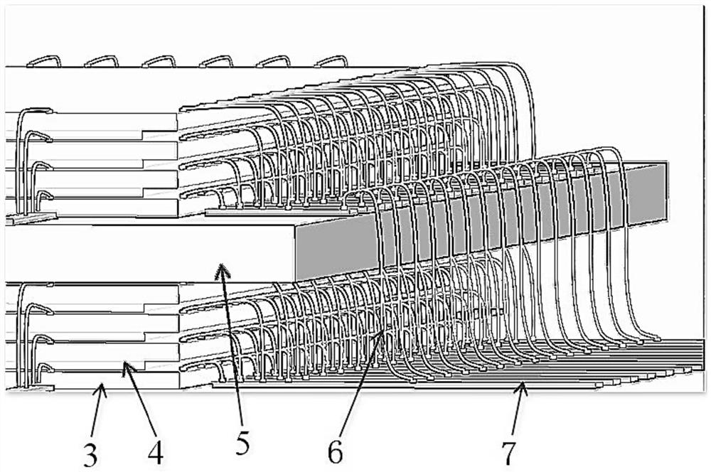
[0038] 1) Bonding the lowest chip 3 of one group of multi-chip stacking assembly units on the shell substrate, and bonding to the shell substrate by reverse bonding process; bonding the bottommost chip 3 of another group of multi-chip stacking assembly units The underlying chip 3 is bonded to the film substrate adapter plate 5, and bonded to the film substrate adapter plate 5 through a reverse bonding process;

[0039] 2) For the package substrate and the film substrate adapter plate 5 respectively, bond the gasket 4 on the bottom chip 3, and bond the chip 3 on the gasket 4;

[0040] Repeat successively to first bond the gasket 4 on the chip 3, then bond the chip 3 on the gasket 4, and make a multi-chip stack assembly unit on the shell substrate and the film substrate adapter plate 5 respectively; Before the gasket 4, the chip 3 is resp...

Embodiment

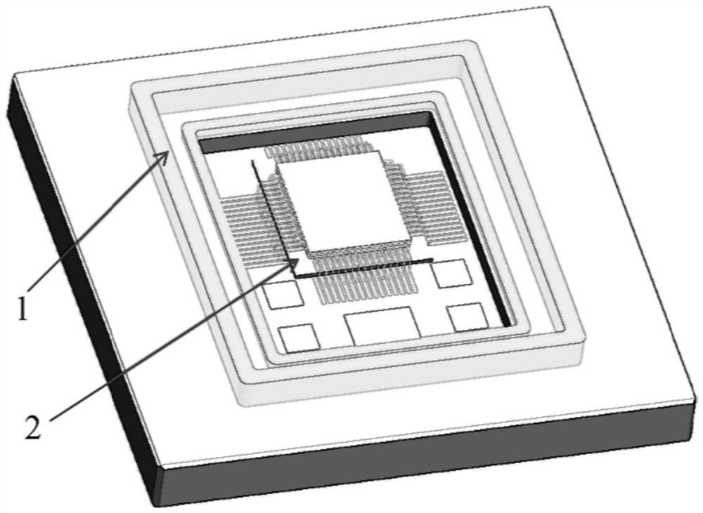
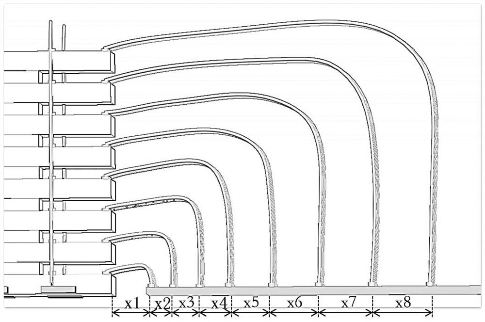
[0060] see figure 1 , figure 2 and Figure 4 , is the packaging structure of the multi-layer chip stack assembly of the present invention. In a specific embodiment, an eight-layer chip stack assembly 2 based on film substrate transfer is formed, wherein the cantilever sandwich type eight-layer chip stack assembly includes 8 super Thin chip, 7 silicon spacers and 1 thin film interposer substrate. The process steps of its preparation process are as follows:

[0061] (1) According to the drawings and materials, observe and determine the bonding area and bonding orientation of the chip 3 under a low-magnification microscope;

[0062] (2) Dip an appropriate amount of adhesive with a dispensing tungsten needle (stir the adhesive at least once every 1 hour, and stir for 2s to 3s each time), and apply it on the center of the chip bonding area. The adhesive should be Approximately coated into the shape of the effective bonding surface of the chip 3 to be bonded or an array of unif...


PUM

PropertyMeasurementUnit
Thicknessaaaaaaaaaa
Lengthaaaaaaaaaa
Sizeaaaaaaaaaa

Abstract

The invention discloses a multi-layer chip laminated assembly packaging structure and a preparation process thereof and belongs to the technical field of multi-layer chip packaging. The multi-layer chip laminated assembly packaging structure comprises multi-chip laminated assembly units and thin film substrate adapter plates, wherein the multi-chip laminated assembly units and the thin film substrate adapter plates are arranged in a tube shell; the thin film substrate adapter plates are arranged between the adjacent multi-chip laminated assembly units; a tube shell gold conduction band is arranged on the bottom surface of the tube shell, and adapter plate gold conduction bands are arranged on the thin film substrate adapter plates; the multi-chip laminated assembly units arranged above the thin film substrate adapter plates are connected with the adapter plate gold conduction bands through bonding wires, and the bonding wires are led out from the adapter plate gold conduction bands to be connected with the tube shell gold conduction band; and a bonding wire is led out from the multi-chip laminated assembly unit at the bottom layer and is connected with the tube shell gold conduction band. According to the preparation process, a forward bonding process and a reverse bonding process are matched with each other, so that the defect that the number of chip lamination layers is limited by an existing bonding process is overcome, the length requirement of a bonding area in a multi-layer chip laminated assembly is reduced, and the sealing packaging requirement is met.

Description

technical field [0001] The invention belongs to the technical field of multilayer chip packaging, and relates to a multilayer chip stack assembly packaging structure and a preparation process thereof. Background technique [0002] As a new packaging form, three-dimensional stacked chip packaging promotes the development of electronic products in the direction of high density, high reliability, low power consumption, high speed and miniaturization. Chip-on-chip packaging technology is to stack multiple chips in the vertical direction and use traditional wire bonding structures for interconnection. Common three-dimensional chip stack structures include pyramid, cross and cantilever sandwich. The area of ​​pyramid-shaped stacked chips can only increase sequentially from top to bottom, and the bonding terminals of cross-shaped stacked chips can only be on both sides of the chip; these two structures largely limit the application of stacking. The cantilever sandwich stack struc...

Claims


Application Information

Patent Timeline
IPC IPC(8): H01L23/498H01L25/065H01L25/18H01L23/49H01L23/492H01L21/60
CPCH01L23/49811H01L24/48H01L24/83H01L24/85H01L25/0657H01L25/18H01L23/492H01L2224/48091H01L2224/48229H01L2224/48247
Inventor 张现顺郑旭升赵国良刘宗溪周明汤淑莉袁海庞宝忠杨宇军郝沄
Owner XIAN MICROELECTRONICS TECH INST
Learn More