
Fmcw lidar system

An optical fiber and optical fiber coupling technology, applied in the field of laser detection, can solve the problems of intermediate frequency signal annihilation, low system signal-to-noise ratio, insertion loss, etc.

Pending Publication Date: 2021-09-10
SUTENG INNOVATION TECH CO LTD
View PDF8 Cites 4 Cited by
  • Summary
  • Abstract
  • Description
  • Claims
  • Application Information

AI Technical Summary

Problems solved by technology

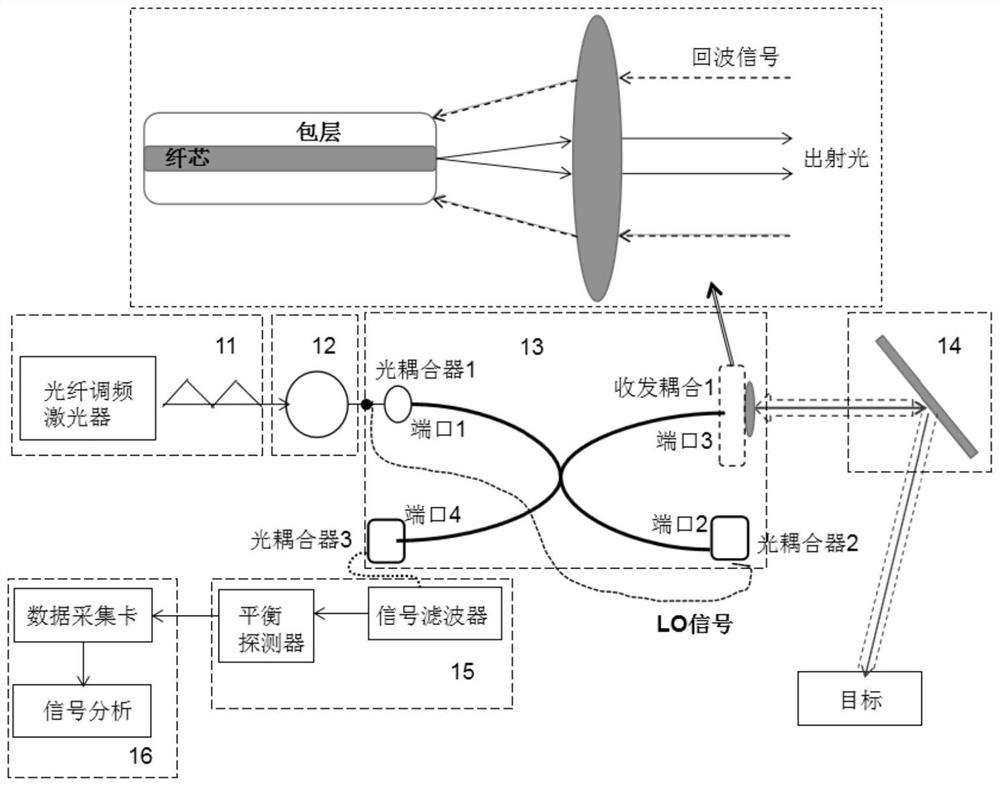
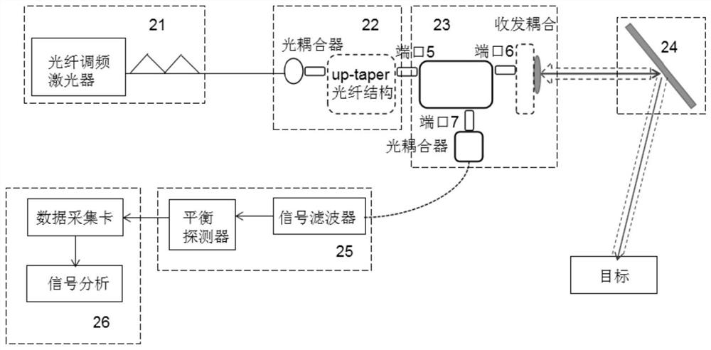
[0004] At present, in the FMCW lidar system, it is often necessary to use a circulator to complete the transmission of the outgoing signal and the reception of the echo signal. The circulator often has insertion loss and strong echo interference, which leads to a low or even real signal-to-noise ratio of the system. The intermediate frequency signal is completely annihilated and cannot be demodulated, resulting in the inability to accurately measure the position information of the target object

Method used


Image

  • Fmcw lidar system
  • Fmcw lidar system
  • Fmcw lidar system

Examples


Embodiment Construction

[0043] The following will clearly and completely describe the technical solutions in the embodiments of the application with reference to the drawings in the embodiments of the application. Apparently, the described embodiments are only some of the embodiments of the application, not all of them. Based on the embodiments in this application, all other embodiments obtained by persons of ordinary skill in the art without making creative efforts belong to the scope of protection of this application.

[0044]In the description of the present application, it should be understood that the terms "first", "second" and so on are used for descriptive purposes only, and should not be understood as indicating or implying relative importance. In the description of the present application, it should be noted that, unless otherwise specified and limited, "including" and "having" and any variations thereof are intended to cover non-exclusive inclusion. For example, a process, method, system, ...


PUM


Abstract

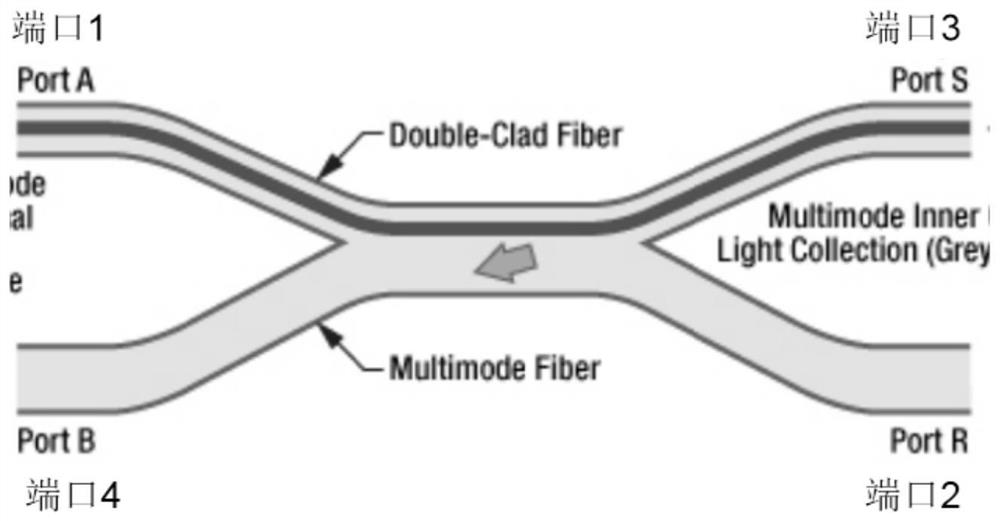
The embodiment of the invention discloses an FMCW LIDAR system. The system comprising an emission module, an optical fiber coupling module, a scanning module and a demodulation module. An output terminal of the emission module is connected to an input terminal of the optical fiber coupling module, a first output terminal of the optical fiber coupling module is connected to the scanning module, and a second output terminal of the optical fiber coupling module is connected to an input terminal of the demodulation module.

Description

technical field [0001] The present application relates to the technical field of laser detection, in particular to an FMCW laser radar system. Background technique [0002] Lidar is a radar system that emits laser beams to detect characteristic quantities such as the position and speed of targets. Its working principle is to send a detection signal to the target, and then compare the received signal reflected from the target with the transmitted signal, and after proper processing, the relevant information of the target can be obtained, such as target distance, azimuth, height, speed, Attitude, even shape and other parameters, so as to detect, track and identify targets such as aircraft and missiles. [0003] For the laser radar system, its ranging principle is to transmit a continuous wave with a linearly changing frequency as the outgoing signal within the frequency sweep period, a part of the outgoing signal is used as a local oscillator signal, and the rest of the outgo...

Claims


Application Information

Patent Timeline
IPC IPC(8): G01S17/32G01S7/481G01S7/493
CPCG01S17/32G01S7/4817G01S7/4818G01S7/4812G01S7/493G01S17/58
Inventor 王超
Owner SUTENG INNOVATION TECH CO LTD
Learn More