Laser cutting machine for precious metal processing
A laser cutting machine and precious metal technology, applied in the field of precious metals, can solve the problems of difficult collection of precious metals, difficult workbench cleaning, high value of precious metals, etc., to achieve the effect of reducing labor intensity, improving work efficiency, and improving collection efficiency
- Summary
- Abstract
- Description
- Claims
- Application Information
AI Technical Summary
Problems solved by technology
Method used
Image
Examples
Embodiment 1
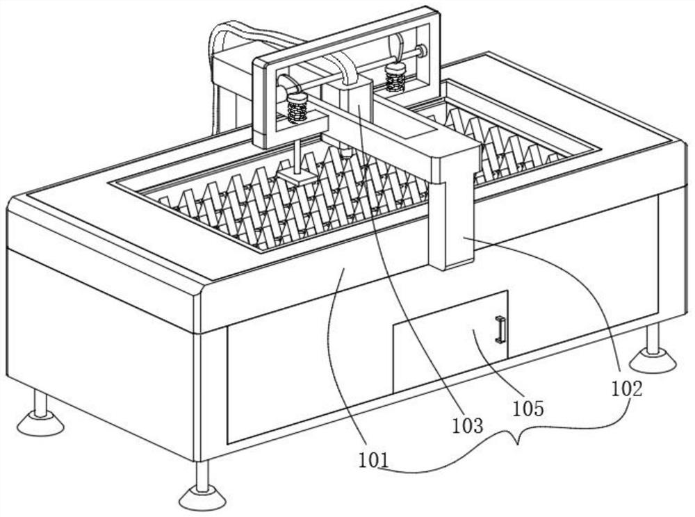
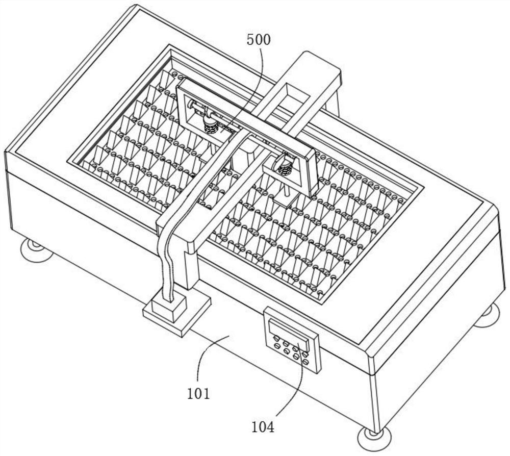
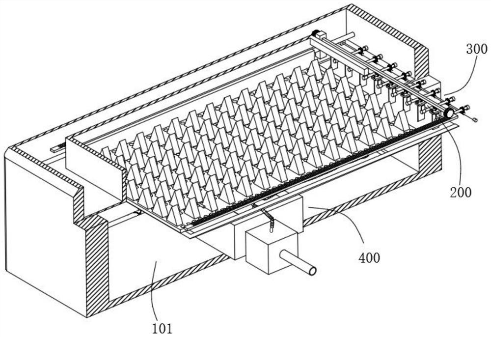
[0047] combine figure 1 , 2 , 3, 4 and 5, the laser cutting machine for precious metal processing provided by the present invention includes a laser cutting machine body 100, a cleaning mechanism 200, a shaking mechanism 300, a collection mechanism 400 and a positioning mechanism 500, and the laser cutting machine body 100 includes a processing Table 101, the connecting frame 102 arranged on the processing table 101, the machine head 103 arranged on the connecting frame 102 and a plurality of through holes provided on the processing table 101, the processing table 101 has a built-in first cavity and a second cavity body, the cleaning mechanism 200 includes a first motor 201 fixed in the first cavity, a screw 202 fixed to the output end of the first motor 201, a slide bar fixed on one side of the first cavity, suitable for the opposite screw 202 and The equipment box sliding on the slide bar, the connecting rod in the equipment box can be installed rotatably, the rack 204 fixe...
Embodiment 2
[0050] combine image 3 and 6 As shown, on the basis of Embodiment 1, the shaking mechanism 300 includes a second motor 301 fixed in the first cavity, a rotating shaft fixed at the output end of the second motor 301, a plurality of worms 303 arranged on the rotating shaft, and Rotate a plurality of rotating shafts installed on the inner wall of the first cavity, the worm wheel 302 that is fitted on the rotating shaft and meshed with the worm 303 for transmission, and the transmission plate 304 fixed on the rotating shaft, the second motor 301 starts to drive the rotating shaft to rotate, and the worm 303 rotates with the rotating shaft, and the worm screw 303 and the worm wheel 302 are meshed for transmission. The worm screw 303 drives the rotating shaft to rotate through the worm wheel 302, and the transmission plate 304 rotates with the rotating shaft, and then the soft brush 205 can be cleaned, and the soft brush can be cleaned. The powder contaminated on the 205 is cleane...
Embodiment 3
[0053] combine image 3 and 7 As shown, in the above embodiment, the collection mechanism 400 includes a hopper 401 fixed in the second cavity and a collection box arranged at the bottom of the hopper 401. The hopper 401 is located below the through hole, and the falling precious metal powder falls into the Into the guide hopper 401, and then into the collection box, the powder can be gathered together, which is convenient for the staff to take the powder away.
[0054] Specifically, the collection mechanism 400 also includes a fan 407 fixed in the second cavity, a guide box 405 arranged in the guide hopper 401 and connected to the fan 407 through a pipeline, and stoppers fixed on both sides of the guide box 405. block, a plurality of guide tubes 406 fixed on the guide box 405, and a filter cover fixed on the guide tube 406, the end of the limit block is slidably connected with the inner wall of the guide hopper 401 through a chute, and the fan 407 starts The wind is used to...
PUM
 Abstract
Description
Claims
Application Information
 - R&D
- Intellectual Property
- Life Sciences
- Materials
- Tech Scout
- Unparalleled Data Quality
- Higher Quality Content
- 60% Fewer Hallucinations
Browse by: Latest US Patents, China's latest patents, Technical Efficacy Thesaurus, Application Domain, Technology Topic, Popular Technical Reports.
© 2025 PatSnap. All rights reserved.Legal|Privacy policy|Modern Slavery Act Transparency Statement|Sitemap|About US| Contact US: help@patsnap.com


