Grooving pipe laying device

A grooving and equipment technology that is applied to mining equipment, earth movers/excavators, earth drilling and mining, etc., and can solve problems such as large manpower and material inputs and low operating efficiency

Pending Publication Date: 2021-09-14
CHINA RAILWAY ENGINEERING EQUIPMENT GROUP CO LTD
View PDF11 Cites 2 Cited by
  • Summary
  • Abstract
  • Description
  • Claims
  • Application Information

AI Technical Summary

Problems solved by technology

[0004] The purpose of the present invention is to provide a grooving pipe laying equipment to solve the technical problems of large manpower and material resources and low operating efficiency in the construction process of shallow buried pipe open excavation in the prior art

Method used


Image

  • Grooving pipe laying device
  • Grooving pipe laying device
  • Grooving pipe laying device

Examples


Embodiment 1

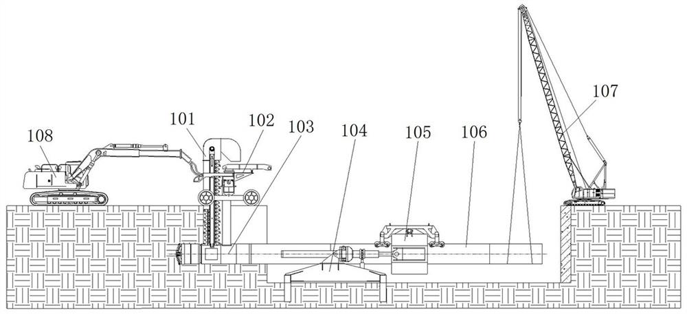
[0044] Such as figure 1 As shown, the grooving pipe laying equipment includes a bucket lifting device 101, a traveling device 102, a driving device 103, an underframe 104, a pipe clamping device 105, a crane 107 and a power unit 108; The device 103, the chassis 104 and the clamping device 105 are all in the originating shaft, the power unit 108 is arranged in front of the originating shaft to provide hydraulic power to each device, and the crane 107 is arranged in the rear of the originating shaft for hoisting pipelines 106; the clamping device 105 is arranged behind the underframe 104 for clamping the pipeline; the excavation device 103 is arranged in front of the underframe 104 for forward excavation; the bucket lifting device 101 and the traveling device 102 are both arranged on the above the device 103.

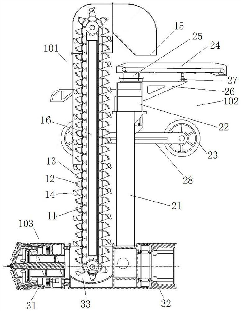
[0045] Such as figure 2 with Figure 4As shown, the excavation device 103 includes a front housing 31 and a rear housing 32, and a deviation correction oil cylinder 3...

Embodiment 2

[0073] The difference between this embodiment and Embodiment 1 is that in Embodiment 1, the groove cutting and pipe laying equipment includes a traveling device 102, and the traveling device 103 is connected to the excavation device 103 through the second column 21, and the muck is lifted by the bucket lifting device 101. The slag outlet falls on the slag conveyor belt 24 of the traveling device 102, and falls on one side of the ditch through the slag discharge end of the slag conveyor belt 24. In this embodiment, the groove cutting and pipe laying equipment does not include a traveling device, and the slag outlet of the bucket lifting device is located on one side of the groove.

Embodiment 3

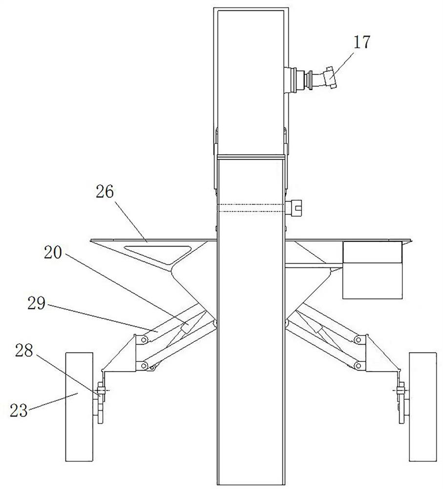
[0075] The difference between this embodiment and Embodiment 1 is that in Embodiment 1, two sets of road wheels 23 are respectively connected to the walking frame 22 through a four-bar linkage mechanism 29, and the walking frame 22 is provided with a road wheel adjustment oil cylinder 20, and the road wheel adjustment The oil cylinder 20 makes the road wheels 22 always be supported on the ground by adjusting the four-bar linkage 29 . In this embodiment, the two sets of walking wheels are vertically slidably assembled on the walking frame, and the walking frame is provided with a walking wheel adjustment oil cylinder, which directly drives the walking wheels to move vertically, so that the walking wheels are always supported on the on the ground.


PUM


Abstract

The invention relates to a grooving pipe laying device. The grooving pipe laying device comprises a bottom frame, a pipe clamping device, a tunneling device, a bucket type lifting device and a scraper, wherein the pipe clamping device is arranged behind the bottom frame and used for clamping a pipeline, and a thrust cylinder is arranged between the pipe clamping device and the bottom frame; the tunneling device is arranged in front of the bottom frame and used for tunneling forwards; the tunneling device is provided with a residue storage groove, an opening of the residue storage groove faces upwards, and the residue storage groove is used for storing residue soil cut by the tunneling device; the bucket type lifting device is arranged in the vertical direction, the lower end of the bucket type lifting device is located in the residue storage groove, the bucket type lifting device is provided with a lifting bucket, the lifting bucket is used for lifting the residue soil in the residue storage groove upwards, and a residue outlet in the upper end of the bucket type lifting device is located in one side of a groove or above the groove; and the scraper is used for scraping a soil layer above the tunneling device when moving in the vertical direction. By additionally arranging the bucket type lifting device, the residue soil is conveyed to the ground in the vertical direction and discharged into the groove or one side of the groove, and the problem that the residue discharging efficiency of the tail is low when the pipeline is laid for a long distance is solved.

Description

technical field [0001] The invention relates to a groove-cutting pipe-laying equipment, which is suitable for the non-excavation field of long-distance shallow-buried pipes. Background technique [0002] In the construction of shallow buried pipelines, horizontal directional drilling, pipe jacking machines and open cut methods are usually used for construction. Horizontal directional drilling is widely used, and has the characteristics of not hindering traffic, occupying a small space, and fast construction speed, but at the same time, it also has disadvantages such as poor control of surface settlement, small strata adaptability range, and short excavation distance; small-diameter pipe jacking machines also have The environmental impact is small, but the existing small-diameter pipeline laying equipment generally adopts muddy water slag discharge at the tail. As the pipeline laying distance becomes longer and longer, it is necessary to stop and connect the pipeline repeated...

Claims


Application Information

Patent Timeline
Patent Type & Authority Applications(China)
IPC IPC(8): E02F5/10E02F5/14E02F3/08E02F3/12E02F3/14E21D9/087E21D9/12
CPCE02F5/10E02F5/14E02F3/08E02F3/082E02F3/12E02F3/141E21D9/087E21D9/12E21D9/124
Inventor 蒋鹏鹏万国伟孙英杰范磊袁征闫扬义冯猛
Owner CHINA RAILWAY ENGINEERING EQUIPMENT GROUP CO LTD
Why Eureka
Try Eureka