Self-adaptive optical system

A technology of adaptive optics and light beams, applied in the field of telescopic imaging, can solve problems such as inability to achieve high-resolution imaging, inability to accurately obtain centroid and wavefront information, and lower detection signal-to-noise ratio

Inactive Publication Date: 2021-09-14
CHANGCHUN INST OF OPTICS FINE MECHANICS & PHYSICS CHINESE ACAD OF SCI
View PDF4 Cites 5 Cited by
  • Summary
  • Abstract
  • Description
  • Claims
  • Application Information

AI Technical Summary

Problems solved by technology

The existing Shaker-Hartmann wavefront sensor cannot work normally in the background of strong skylight during the day, so ground-based telescopes cannot achieve high-resolution imaging under the background of strong skylight in the daytime
Under the background of strong skylight in daytime, the sub-apertures of the microlens array of the Shack-Hartmann wavefront s

Method used


Image

  • Self-adaptive optical system

Examples


Embodiment Construction

[0029] Embodiments of the present invention will be further described in detail below in conjunction with the accompanying drawings and examples. It should be noted that, in the case of no conflict, the embodiments of the present invention and the features in the embodiments can be combined with each other. Based on the embodiments of the present invention, all other embodiments obtained by persons of ordinary skill in the art without creative efforts fall within the protection scope of the present invention.

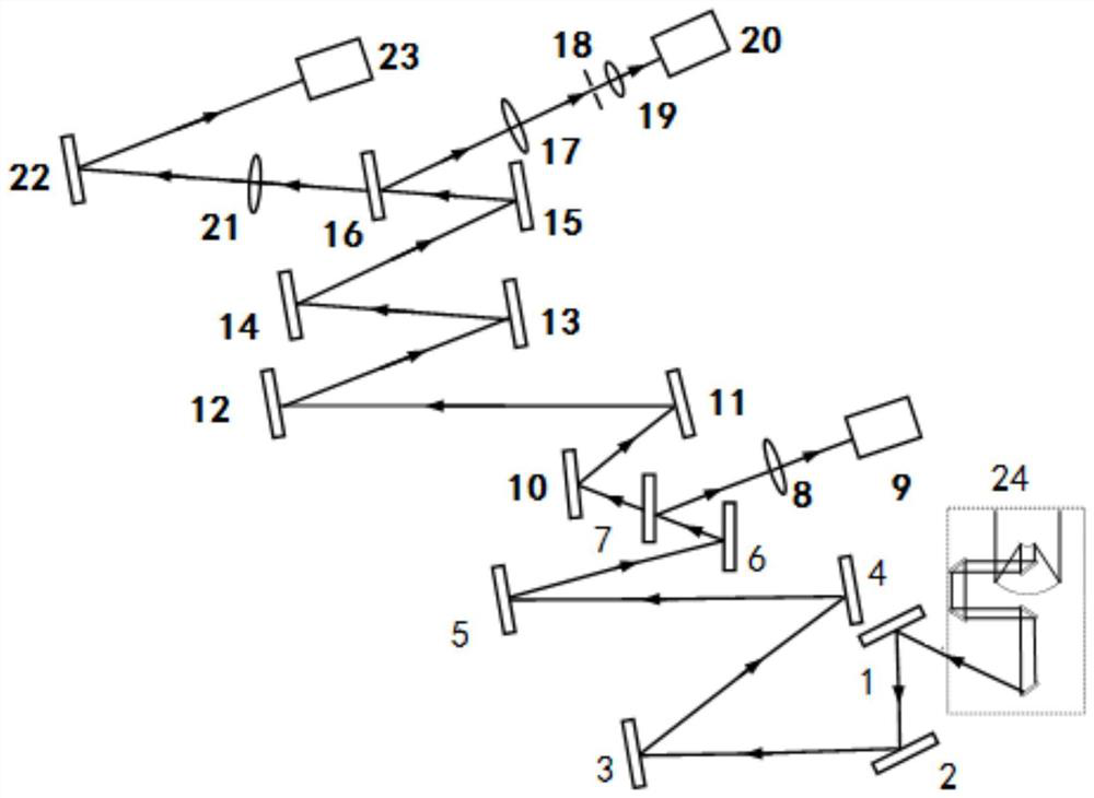
[0030] figure 1 A schematic structural diagram of an adaptive optics system according to an embodiment of the present invention is shown.

[0031] The present invention provides an adaptive optical system, including a first reflector 1, a second reflector 2, a spherical mirror 3, a primary beam expander mirror group, a primary tracking unit, a secondary tracking and high-order aberration closed-loop correction unit, imaging unit. The primary tracking unit includes: a...


PUM


Abstract

The invention relates to a self-adaptive optical system. The self-adaptive optical system comprises a reflector group, a spherical mirror, a first-stage beam expander group, a first-stage tracking unit, a second-stage tracking and high-order aberration closed-loop correction unit and an imaging unit, the first-stage tracking unit comprises a first fast control reflector, a first spectroscope, a tracking imaging lens and a short wave infrared tracking camera; and the second-stage tracking and high-order aberration closed-loop correction unit comprises a second fast control reflector, a second-stage beam expander group, a piezoelectric deformable mirror, a third-stage beam expander group, a second spectroscope, a first Shack-Hartmann wavefront sensor beam shrinking lens, a Hartmann field diaphragm, a second Shack-Hartmann wavefront sensor beam shrinking lens, and a Shack-Hartmann wavefront sensor. The problem that the self-adaptive optical system cannot work normally in the visible light band in the background of strong daylight in the daytime is solved.

Description

technical field [0001] The invention belongs to the technical field of telescopic imaging, and in particular relates to an adaptive optical system. Background technique [0002] Ground-based telescopes are important tools for humans to conduct remote sensing observations of space debris, celestial bodies or the earth. With the continuous development of ground-based telescopes, the adaptive optics system has become a necessary means to improve the imaging resolution of ground-based large-aperture photoelectric telescopes because it can correct the wavefront distortion caused by atmospheric turbulence. There are still many problems with ground-based telescopes for space debris detection. Conventional adaptive optics ground-based telescopes work in the visible light range. In practical applications, some space debris is blocked by the earth and can only be observed near dawn and evening, and some space debris only appears above a fixed area and in a fixed place during the day...

Claims


Application Information

Patent Timeline
IPC IPC(8): G02B26/08G02B23/02G02B5/00G02B27/10G02B27/09
CPCG02B26/0825G02B23/02G02B5/005G02B27/1006G02B27/0927
Inventor 王建立姚凯男徐立杨乐强
Owner CHANGCHUN INST OF OPTICS FINE MECHANICS & PHYSICS CHINESE ACAD OF SCI
Why Eureka
Try Eureka