Centralized power-adjustable BMS passive equalization circuit

A passive equalization, centralized technology, applied in charge equalization circuits, current collectors, circuit devices, etc., can solve problems such as low efficiency, complex control, and difficulty in reducing

Active Publication Date: 2021-09-14
SHANGHAI YUYUAN POWER TECH CO LTD
View PDF11 Cites 0 Cited by
  • Summary
  • Abstract
  • Description
  • Claims
  • Application Information

AI Technical Summary

Problems solved by technology

However, each battery needs to be connected with an external MCSFET and balancing resistor, which will take up a lot of space, complex layout, and complicated control
[0005] 3. Due to the complexity of the circuit and the fixed equalization circuit, the equalization power cannot be adjusted, only the equalization time can be adjusted, and the efficiency is extremely low
[0006] 4. If you want to increase the balance power, you need to connect more resistors in parallel in each equalization circuit. The power resistors are large and cannot be miniaturized and compacted, which brings great difficulties to the circuit PCB design.
[0007] 5. Since the balancing resistors are connected in parallel to sufficient power according to the number of batteries and then connected in series, the space required for the whole balancing circuit to be connected in series is very large, and it is difficult to reduce

Method used


Image

  • Centralized power-adjustable BMS passive equalization circuit
  • Centralized power-adjustable BMS passive equalization circuit

Examples


Embodiment 1

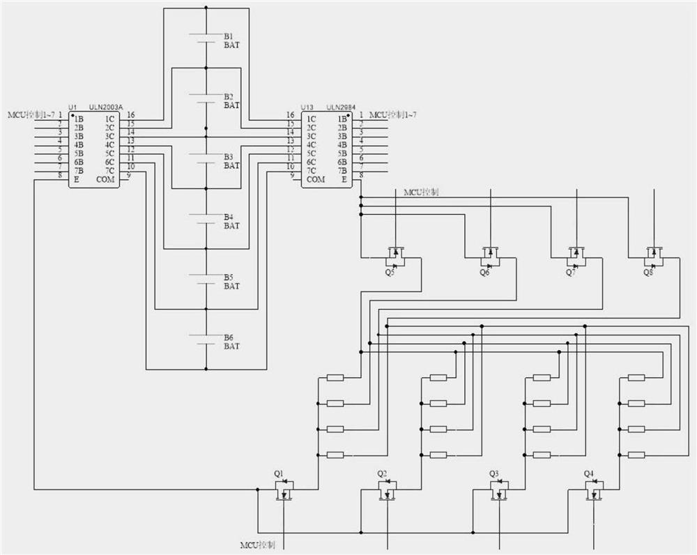
[0027] Embodiment 1: If the MCU judges that battery B3 needs to be balanced, it sends a high level to the 3B pin of the U1 Darlington tube array, and the corresponding 3C pin is turned on, and the positive current of the battery B3 flows from the 3C pin to the E lead The pin flows from the E pin to the balance resistor array. At the same time, the MCU needs to change the high level of the 4B pin of the U2 Darlington tube array to a low level, and the corresponding 4C pin is turned on, and the current of the equalizing resistor array flows from the E pin to the 4C pin, and finally flows back to the Battery B3 negative terminal.

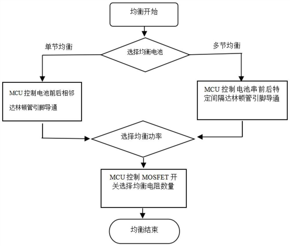
[0028] The single-cell battery balancing method is shown in the above example. The MCU controls the U1 Darlington tube array and the U2 Darlington tube array, connects the pins corresponding to the positive and negative poles of the battery, and connects the battery to the balancing resistor array.

[0029] Multi-cell battery balancing, that is, the M...

Embodiment 2

[0030] Embodiment 2: If the MCU judges that batteries B3 and B4 need to be balanced, a high level is sent to the 3B pin of the U1 Darlington tube array, and the corresponding 3C pin is turned on, and the positive current of the battery B3 flows from the 3C pin to E pin, from the E pin to the balance resistor array. At the same time, the MCU needs to change the high level of the 5B pin of the U2 Darlington tube array to a low level, and the corresponding 5C pin is turned on, and the current of the equalizing resistor array is diverted from E to the 5C pin, and finally flows back to the battery B4 negative pole.

[0031] Two non-adjacent single-cell batteries are balanced, and the microcontroller sends two PWM signals with the same frequency and opposite phases, respectively controlling the Darlington tubes corresponding to the positive and negative poles of the two batteries to be connected, and the two batteries are alternately connected to the balance resistor array.

Embodiment 3

[0032] Embodiment 3: If the MCU judges that batteries B3 and B5 need to be balanced, two PWM signals with the same frequency and opposite phases are sent to the 3B and 5B pins of the U1 Darlington tube array, and the positive currents of batteries B3 and B5 are alternately drawn by 3C The pin and 5C pin flow to the E pin, and the E pin flows to the balance resistor array. At the same time, the MCU needs to change the high level of the 4B and 6B pins of the U2 Darlington tube array to a low level through two PWM signals, and the corresponding 4C pins and 6C pins are respectively turned on, and the balanced current is controlled by E The pins flow in and return to the negative terminals of batteries B3 and B5, respectively.

[0033] Two strings of non-adjacent battery strings are balanced, and the single-chip microcomputer sends two PWM signals with the same frequency and opposite phases, respectively controlling the Darlington tubes corresponding to the total positive and negat...


PUM


Abstract

The invention relates to the related field of new energy lithium battery energy storage, in particular to a centralized power-adjustable BMS passive equalization circuit which comprises six batteries B1 to B6, a U1 Darlington tube array, a U2 Darlington tube array, four equalization input MOS tubes Q1 to Q4, four equalization output MOS tubes Q5 to Q8 and 16 equalization resistors. According to the invention, a centralized equalization circuit is adopted, so that the equalization circuit does not need to be designed for each battery. The equalization circuit is simple in structure, compact in space, small in driving current, capable of adapting to direct driving of an equalization chip or driving of a single-chip microcomputer, flexible in design, capable of adjusting equalization power according to needs, large in equalization resistor arrangement area and beneficial to heat dissipation due to heat dissipation. The control is flexible and can be adjusted as required; the equalization circuit suitable for various powers and various currents can be flexibly combined through the resistor matrix, the equalization current is large and can reach 1A or above, and the equalization power can reach 3W or above; and the centralized equalization circuit does not need to configure equalization for each path of battery, so that a large amount of space can be saved, and great convenience is brought to compact circuit design.

Description

technical field [0001] The invention relates to the field related to new energy lithium battery energy storage, in particular to a centralized power adjustable BMS passive equalization circuit. Background technique [0002] With the country's policy inclination towards the new energy industry, lithium batteries and BMS systems are widely used in many fields. In order to maintain the consistency of lithium batteries in the charging and discharging process, it is necessary to perform passive balancing on batteries with higher voltages. However, the existing The equalization circuit has the following problems: [0003] 1. Some of the existing passive equalization circuits are based on passive equalization chips, but the current passing through the chip cannot be very large, and the efficiency is very low. [0004] 2. Some passive equalization circuits are based on equalization chips to control peripheral MOSFETs, and external equalization circuits. However, each battery needs...

Claims


Application Information

Patent Timeline
Patent Type & Authority Applications(China)
IPC IPC(8): H02J7/00
CPCH02J7/0019H02J7/007
Inventor 尚德华杜鹏飞
Owner SHANGHAI YUYUAN POWER TECH CO LTD
Why Eureka
Try Eureka