
Heat storage type waste heat recovery device

A waste heat recovery device and waste heat recovery technology, which are applied in lighting and heating equipment, steam generation methods using heat carriers, steam/steam condensers, etc., can solve problems such as low heat recovery efficiency, improve recovery efficiency, and improve power generation. Efficiency, the effect of improving the generation efficiency

Pending Publication Date: 2021-09-17
浙江诚邦新能源科技有限公司
View PDF3 Cites 2 Cited by
  • Summary
  • Abstract
  • Description
  • Claims
  • Application Information

AI Technical Summary

Problems solved by technology

[0004] The purpose of the present invention is to provide a heat storage type waste heat recovery device to solve the problem of low heat recovery efficiency of the waste heat recovery device proposed in the above background technology

Method used


Image

  • Heat storage type waste heat recovery device
  • Heat storage type waste heat recovery device
  • Heat storage type waste heat recovery device

Examples


Embodiment Construction

[0023] The following will clearly and completely describe the technical solutions in the embodiments of the present invention with reference to the accompanying drawings in the embodiments of the present invention. Obviously, the described embodiments are only some, not all, embodiments of the present invention.

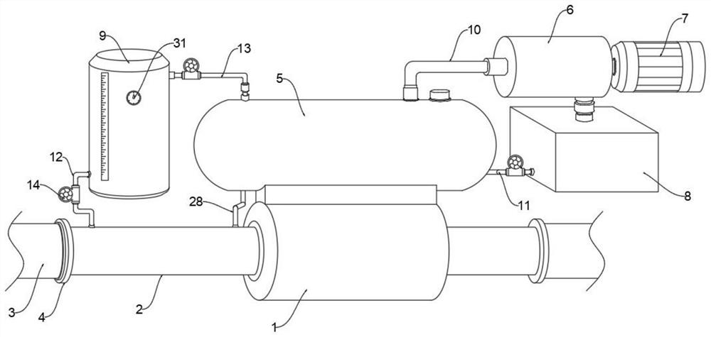
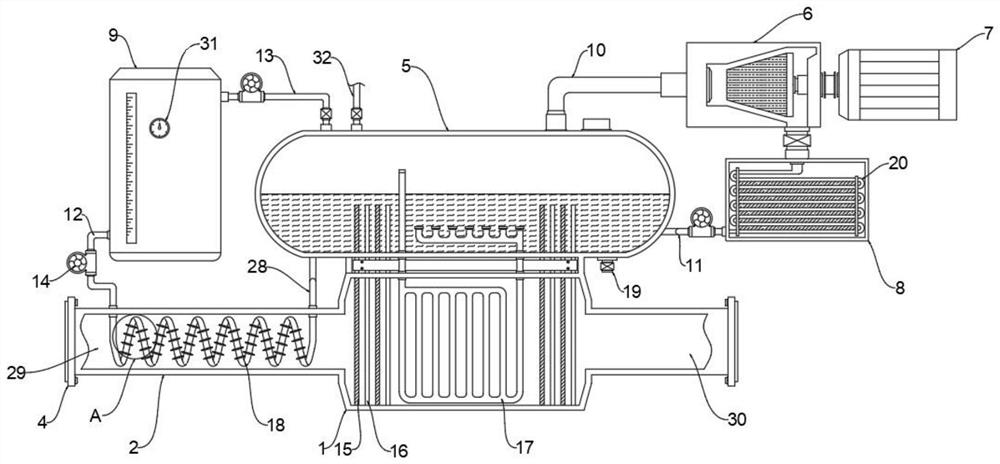
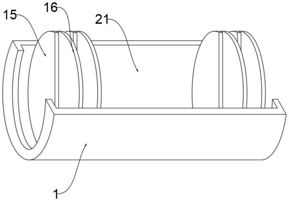
[0024] see Figure 1-5 , an embodiment provided by the present invention: a heat storage type waste heat recovery device, including a flue connecting pipe 2 integrally arranged on both sides of the waste heat recovery pipe 1, and a flue gas inlet is arranged at one end of the flue connecting pipe 2 on one side 29. One end of the flue connecting pipe 2 on the other side is provided with a flue gas outlet 30, and the flue gas exhaust pipe 3 is installed on both sides of the flue connecting pipe 2, and the inside of the flue connecting pipe 2 at one end of the flue gas inlet 29 is installed There is a heat exchange spiral pipe 18, and the flue gas exhaust pipe 3 and the...


PUM


Abstract

The invention discloses a heat storage type waste heat recovery device, relates to the technical field of waste heat recovery, and aims at solving the problem that an existing waste heat recovery device is low in heat recovery efficiency. Flue connecting pipes are integrally arranged on the two sides of a waste heat recovery pipe, a flue gas inlet is formed in one end of the flue connecting pipe on one side, a flue gas outlet is formed in one end of the flue connecting pipe on the other side, and flue gas discharge pipes are installed on the two sides of the flue connecting pipes; a heat exchange spiral pipe is installed in the flue connecting pipe located at the end where the flue gas inlet is located, the flue gas discharge pipes and the flue connecting pipes are sealed and fixed through connecting flanges, a steam pocket is welded and fixed to the upper portion of the waste heat recovery pipe, and a flue gas heat exchange cavity is formed in the waste heat recovery pipe; and the two sides of the interior of the flue gas heat exchange cavity are each provided with a heat exchange plate assembly, a steam auxiliary heating device is arranged in the middle of the interior of the flue gas heat exchange cavity, and the upper end of the steam auxiliary heating device extends into the steam pocket.

Description

technical field [0001] The invention relates to the technical field of waste heat recovery, in particular to a heat storage type waste heat recovery device. Background technique [0002] Waste heat refers to the sensible heat and latent heat that have not been rationally utilized in the original design in the energy-consuming devices of industrial enterprises that have been put into operation due to the limitations of history, technology, ideas and other factors. It includes waste heat of high-temperature exhaust gas, waste heat of cooling medium, waste heat of waste steam and waste water, waste heat of high-temperature products and slag, waste heat of chemical reaction, waste heat of combustible waste gas and liquid, waste heat, etc. According to the survey, the total waste heat resources of various industries account for about 17% to 67% of their total fuel consumption, and the recyclable waste heat resources are about 60% of the total waste heat resources. The product af...

Claims


Application Information

Patent Timeline
Patent Type & Authority Applications(China)
IPC IPC(8): F22B1/18F28B1/02F28B9/04F28B9/08
CPCF22B1/18F28B1/02F28B9/08F28B9/04
Inventor 赵卫国
Owner 浙江诚邦新能源科技有限公司
Learn More