Master-slave dual-motor transmission, drive system and electric construction vehicle
A transmission device and main motor technology, applied to electric power devices, power devices, electric vehicles, etc., can solve problems such as high cost, difficulty in continuous power coupling control of dual motors, difficulty in meeting the needs of compound drive control, etc., to achieve Low cost, improved power and economy, and improved service life
- Summary
- Abstract
- Description
- Claims
- Application Information
AI Technical Summary
Problems solved by technology
Method used
Image
Examples
Embodiment 1
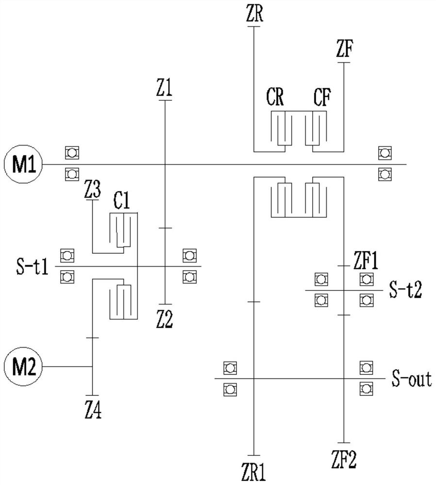
[0040] See attached figure 1 , a master-slave dual-motor transmission device, including a master motor M1, a slave motor M2, a power output shaft S-out, a forward gear clutch CF, a reverse gear clutch CR, a power coupling transmission unit, a first power transmission unit and a second power transmission unit The power transmission unit, the forward gear clutch CF and the reverse gear clutch CR are installed on the output shaft of the main motor M1, and the power coupling transmission unit is connected between the output shaft of the main motor M1 and the output shaft of the slave motor M2. The first power transmission The unit transmission is connected between the forward gear clutch CF and the power output shaft S-out, and the second power transmission unit is transmission connected between the reverse gear clutch CR and the power output shaft S-out,
[0041] The output shaft of the main motor M1 is provided with a first power output terminal, and the power output shaft S-out...
Embodiment 2
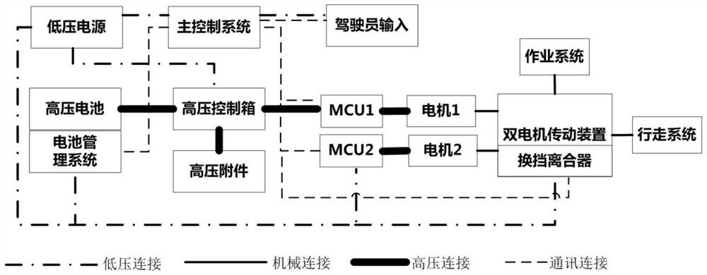
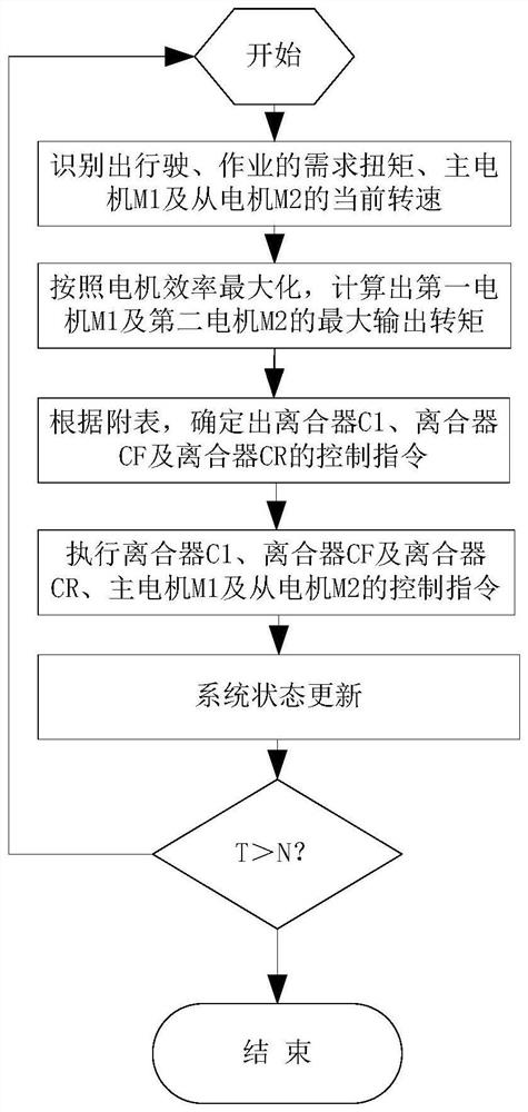
[0055] See attached figure 2 , a master-slave dual-motor drive system, including any one of the above-mentioned master-slave dual-motor transmission device, and also includes a driver operation input terminal, a low-voltage power supply, a power source and a main control system, and the signal connection of the driver operation input terminal To the main control system, the low-voltage power supply provides power for the main control system, the power source provides power for the main motor M1, and the low-voltage power supply provides power for the slave motor M2. The main control system executes the following control process, see the attached image 3 :
[0056] a. According to the driver's operation input terminal information and vehicle status information, identify the current required operation and / or driving torque and the current speed of the main motor M1 and the slave motor M2;
[0057] b. Based on the principle of maximizing motor efficiency, calculate the maximum...
Embodiment 3
[0063] See attached figure 2 , an electric engineering vehicle, including any one of the above-mentioned master-slave dual-motor drive system, and also includes a working system and a walking system, the output shaft of the main motor M1 is connected to the working system, and the power output shaft S-out is connected to the walking system , through the coupling control of the main motor M1 and the slave motor M2 to control the power output to complete the required work and driving functions.
[0064] Compared with the prior art, the advantages of the master-slave dual-motor transmission device, control system and electric engineering vehicle of the embodiment of the present invention are:
[0065] Aiming at the operation and driving power requirements of electric engineering vehicles, the present invention designs a master-slave dual-input-two-output dual-motor transmission device. The main driving motor is directly connected to the hydraulic system and connected to the driv...
PUM
 Abstract
Description
Claims
Application Information
 - R&D
- Intellectual Property
- Life Sciences
- Materials
- Tech Scout
- Unparalleled Data Quality
- Higher Quality Content
- 60% Fewer Hallucinations
Browse by: Latest US Patents, China's latest patents, Technical Efficacy Thesaurus, Application Domain, Technology Topic, Popular Technical Reports.
© 2025 PatSnap. All rights reserved.Legal|Privacy policy|Modern Slavery Act Transparency Statement|Sitemap|About US| Contact US: help@patsnap.com


